Robot having multiple degrees of freedom

Inactive Publication Date: 2000-03-14
GENMARK AUTOMATION
View PDF74 Cites 87 Cited by
  • Summary
  • Abstract
  • Description
  • Claims
  • Application Information

AI Technical Summary

Benefits of technology

9) Continuous motion handling, the "yaw" axis makes it possible to plan and execute continuous path trajectories (FIG. 6) between two cassettes that results in smooth and fast wafer or flat panel handling; in turn, this makes the transported material (wafer, flat panel) and the processing equipment less stressed; the sequence "retract-rotate-extend" which is used to move a wafer from one cassette to another in the classical .theta.RZ scheme is replace by a single moti

Problems solved by technology

There is a problem which is common to all of the above described radial positioning arms.
This problem is that the arms must sit idly by while a workpiece is being worked upon.
A very important problem which exists with present day robotic arm mechanisms is that they can only follow a radial straight line (R) path or a circular (.theta.) path in the R, .theta. plane from one point another.
This provides an overall jerky stop/start motion which can lead to damage to the apparatus over many thousands of operations and which also vibrates the object being moved with possible deleterious effects on product yield.
Also, if there is an obstacle which protrudes into that plane of operation of the arm as may occur in a semiconductor processing operation, an inefficient path must be followed to anything hidden behind or shadowed by that obstacle, namely, a straight line path must be followed to withdraw the arm radially inwardly beyond the obstacle and then radial motion must be imparted to move the end effector of the arm past the obstacle followed by radial outward motion to the desired work station.
Another very important problem which arises in such robotic arm systems is related to loading in cassettes fil

Method used


Image

  • Robot having multiple degrees of freedom
  • Robot having multiple degrees of freedom
  • Robot having multiple degrees of freedom

Examples


Embodiment Construction

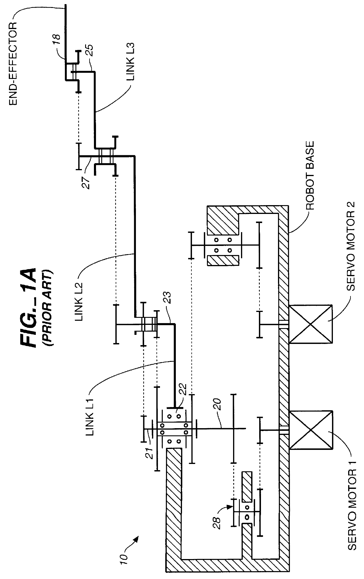
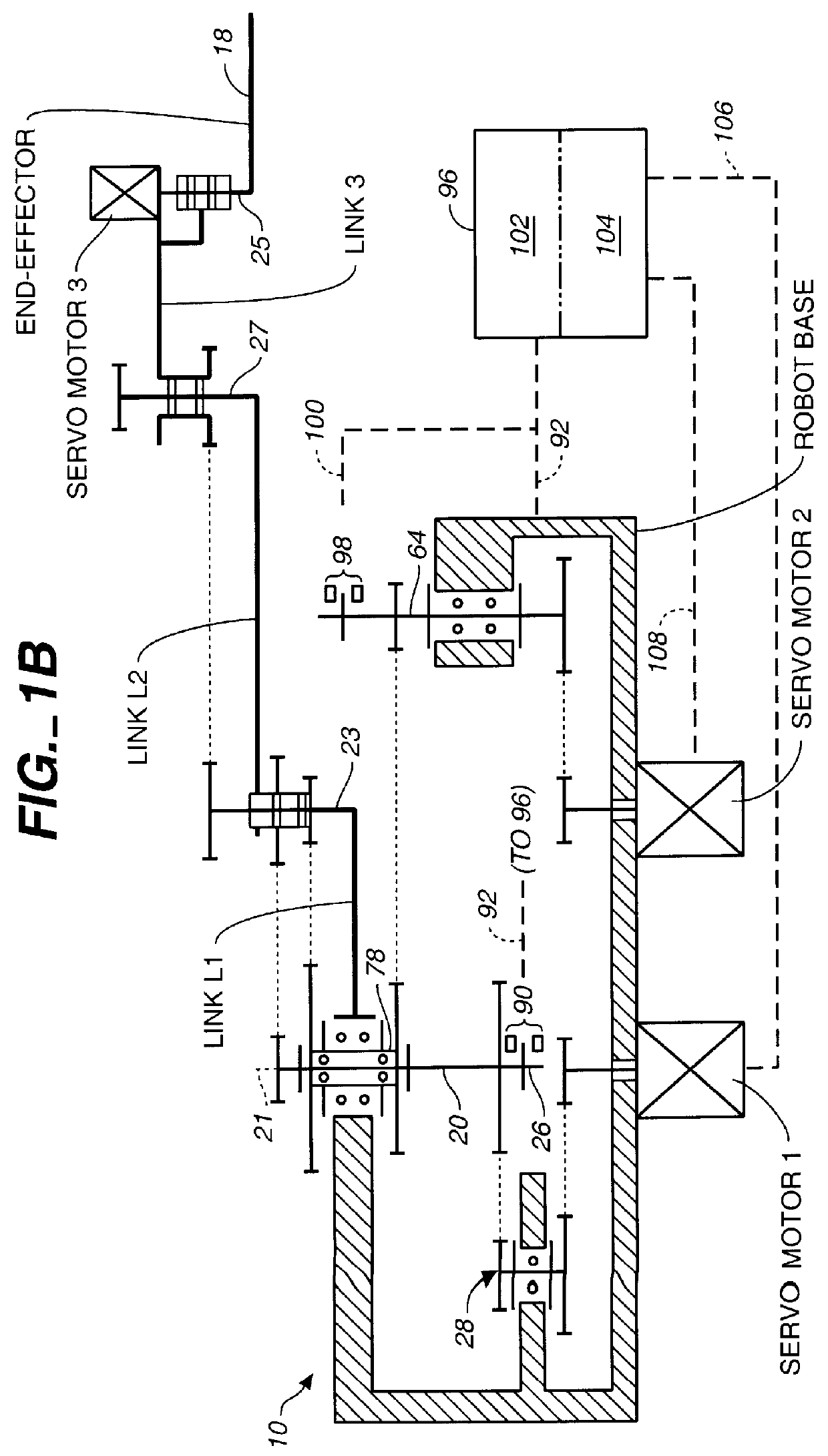
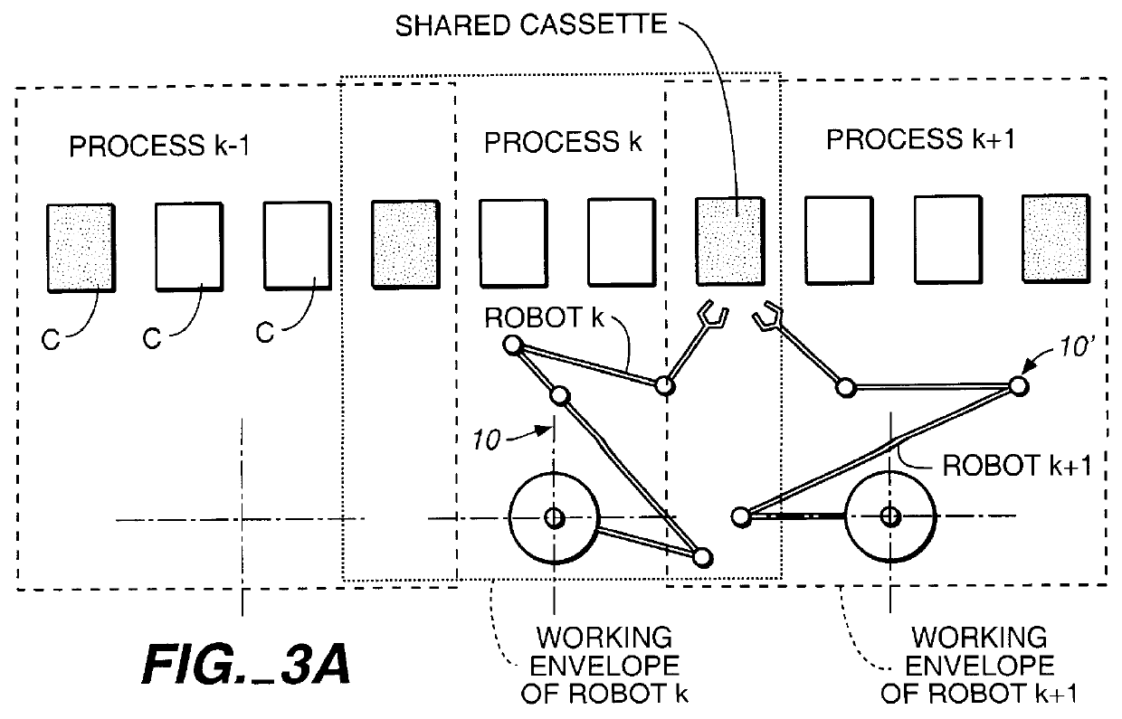
The present invention provides a unique yaw motion to the end effectors of robotic arms which allows the arms to be used more efficiently than can prior art arms which lack yaw motion. In certain embodiments both roll / or pitch motion is provided. The motion of the arm can be controlled via mechanisms which include measuring the rotational rate (and thereby positions) of the radial and rotary drive shafts and of the yaw drive shaft (and the roll and pitch drive shafts, where used) and utilizing a computer to control these quantities such that the end effector of the robotic arm follows a desired path. The arm retains the capability of straight line motion and, indeed, extends this ability to straight line motion in other than the radial direction as well as to an arbitrary trajectory. There are a number of unique features to the invention.

For a better understanding of the invention it should be noted that the terms "belt", "belt means", "pulley" and "pulley means" are, at times, refe...


PUM


Abstract

An improvement is set forth in a robotic arm structure which includes at least two links. theta motion is provided about a primary axis at the proximal end portion of the proximalmost of the links. R motion proceeds radially from the primary axis whereby the distal end portion of the distalmost of the links can be moved in a radially extending straight line. An end effector is pivotally mounted for rotation relative to the distal end portion of the distalmost link about an end effector axis which is parallel to the primary axis. The structure is improved by adding one or more a yaw motor, a roll motor and a pitch motor for rotating the wrist of the arm about the respective axes. A sensor array senses the R, theta , Z and yaw, roll and/or pitch motions and creates and transmits electronic signals representative thereof to a computer controller which monitors and controls the R, theta , Z and yaw, roll and/or pitch motions. Non-radial straight line motion and indeed, in certain embodiments any desired three-dimensional motion, is thereby enabled as is picking up of workpieces such as semiconductor wafers, flat panel displays and data storage disks, which are misaligned in cassettes or at workstations and/or are in cassettes which are misaligned and/or aligned and set up at an angle relative to the usual plane of operation of the arm.

Description

The present invention relates to a precision arm mechanism which will extend and retract in a straight line, including a non-radially extending straight line, and is also movable in a desired non-straight line path. In certain embodiments it can be tilted from its usually vertical axis to correct for misalignment of workpieces. It can pick up and deliver workpieces located at an angle from its plane of normal operation. It is suitable for positioning various objects such as semiconductor wafers, cassettes holding such wafers, panels, computer hard discs, and the like for processing and / or use.BACKGROUND OF INVENTIONThe use of robot arms for positioning and placing objects is well known. Generally, the arms have Z, R and .theta. motion in a conventional cylindrical coordinate system. The capability of providing straight line motion is very important in the processing of semiconductor wafers so as to allow them to be very accurately positioned at a work station where processing steps ...

Claims


Application Information

Patent Timeline
IPC IPC(8): B25J9/16B25J9/10B25J9/06B25J9/18G05B19/18
CPCB25J9/1615G05B2219/40242Y10S414/137Y10S414/136Y10S700/90
Inventor GENOV, GENCOTODOROV, ALEXANDERKOSTOV, LUBOPETKOV, PETERTOTEV, VALENTINBONEV, EUGENESOTIROV, ZLATKO
Owner GENMARK AUTOMATION
Why Eureka
Try Eureka