Method for manufacturing an ultrasonic transducer incorporating an array of slotted transducer elements

a transducer array and ultrasonic technology, applied in ultrasonic/sonic/infrasonic diagnostics, instruments, mechanical vibration separation, etc., can solve the problems of low sensitivity, low frequency response of undesirable narrow band, and non-uniform thickness of the filler layer, so as to improve sensitivity, improve acoustic performance, and improve the effect of bandwidth

Inactive Publication Date: 2000-03-21
GENERAL ELECTRIC CO
View PDF19 Cites 57 Cited by
  • Summary
  • Abstract
  • Description
  • Claims
  • Application Information

AI Technical Summary

Benefits of technology

The present invention is embodied in an ultrasonic transducer array having individual transducer elements that are mechanically focused into an imaging plane, are acoustically matched to the medium being interrogated, and are acoustically isolated from each other along an array axis in the imaging plane, resulting in improved acoustic performance, improved sensitivity, increased bandwidth and improved foc

Problems solved by technology

One drawback of this array is that it provides an undesirable narrow band frequency response and low sensitivity.
In particular, the non-uniform thickness of the filler layer inhibits the transfer of acoustic energy over a broad frequency range from the piezoelectric material into the body being scanned.
Further, narrow band frequency response increases the pulse length of the transmitted acoustic wave and thus limits the array's axial resolution.
Another drawback is that the contiguous acoustic matching layer gives rise to undesirable interelement crosstalk.
One disadvantage of this construction is that the sensitivity of the transducer elements is negatively

Method used


Image

  • Method for manufacturing an ultrasonic transducer incorporating an array of slotted transducer elements
  • Method for manufacturing an ultrasonic transducer incorporating an array of slotted transducer elements
  • Method for manufacturing an ultrasonic transducer incorporating an array of slotted transducer elements

Examples


Embodiment Construction

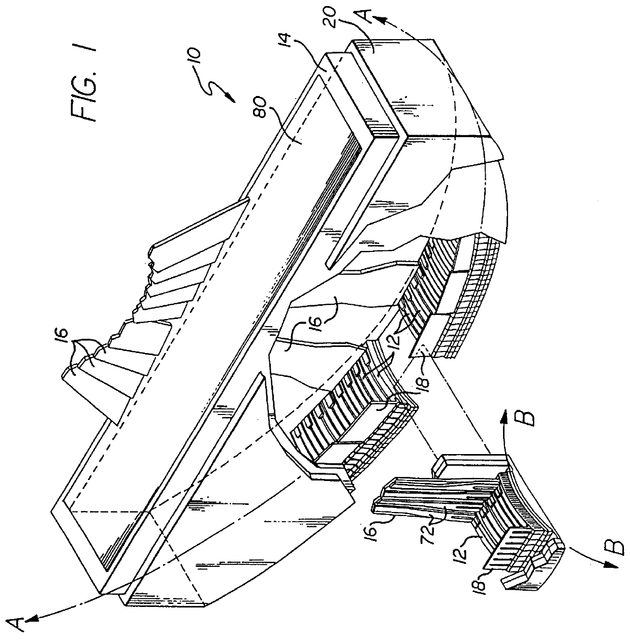
An ultrasonic transducer array 10 made according to the present invention is shown in FIG. 1. The array includes a plurality of individual ultrasonic transducer elements 12 encased within a housing 14. The individual elements are electrically connected to the leads 16 of a flexible printed circuit board and ground foils 18 that are fixed in position by a polymer backing material 80. A dielectric face layer 20 is formed around the array and the housing.

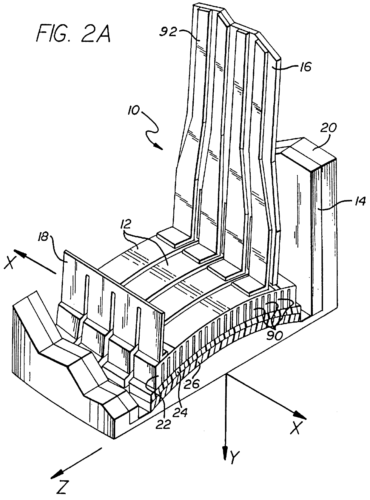
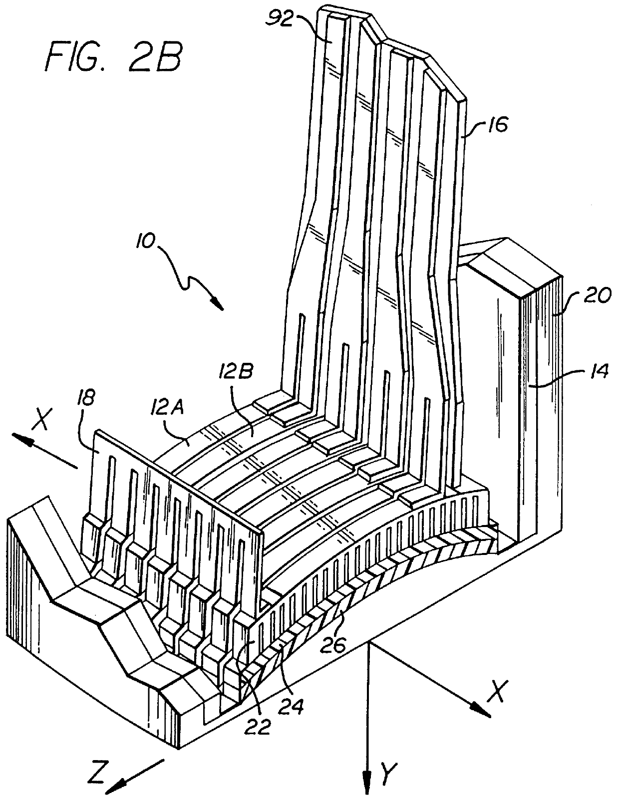
Each individual ultrasonic transducer element 12 is made up of a piezoelectric layer 22, a first acoustic matching layer 24 and a second acoustic matching layer 26 (see also FIG. 2A). The individual elements are mechanically focused into a desired imaging plane (defined by the x-y axes) due to the concave shape of the piezoelectric and adjoining acoustic matching layers. The individual elements are also mechanically isolated from each other along an array axis A located in the imaging plane (as may be defined by the midpoints of the ch...


PUM

PropertyMeasurementUnit
Temperatureaaaaaaaaaa
Electrical conductivityaaaaaaaaaa
Elastomericaaaaaaaaaa

Abstract

An ultrasonic transducer array, and a method for manufacturing it, having a plurality of transducer elements aligned along an array axis in an imaging plane. Each transducer element includes a piezoelectric layer and one or more acoustic matching layers. The piezoelectric layer has a concave front surface overlayed by a front electrode and a rear surface overlayed by a rear electrode. The shape of each transducer element is selected such that it is mechanically focused into the imaging plane. A backing support holds the plurality of transducer elements in a predetermined relationship along the array axis such that each element is mechanically focused in the imaging plane.

Description

BACKGROUND OF THE INVENTIONThis invention relates generally to ultrasonic transducer arrays and, more particularly, to an array having a plurality of individual, acoustically isolated elements that are uniformly distributed along an axis which is straight, curvilinear, or both.Ultrasonic transducer arrays are well-known in the art and have many applications, including diagnostic medical imaging, fluid flow sensing and the non-destructive testing of materials. Such applications typically require high sensitivity and broad band frequency response for optimum resolving power.An ultrasonic transducer array typically includes a plurality of individual transducer elements that are uniformly spaced along an array axis that is straight (i.e., a linear array), or curvilinear (e.g., a concave or convex array). The transducer elements each include a piezoelectric layer. The transducer elements also include one or more overlaying acoustic matching layers, typically each one-quarter wavelength t...

Claims


Application Information

Patent Timeline
IPC IPC(8): B06B1/06G10K11/32G10K11/00B06B1/02G01N29/24A61B8/00H04R17/00H04R31/00
CPCB06B1/0622B06B1/0633B06B1/0692G10K11/32Y10T29/42B06B2201/50B06B2201/56B06B2201/20
Inventor FINSTERWALD, P. MICHAELDOUGLAS, STEPHEN JOSEPHJUST, RICKY GAIL
Owner GENERAL ELECTRIC CO
Why Eureka
Try Eureka