Magneto-optical data storage system

Inactive Publication Date: 2000-04-04
SEAGATE TECH LLC
View PDF31 Cites 19 Cited by
  • Summary
  • Abstract
  • Description
  • Claims
  • Application Information

AI Technical Summary

Problems solved by technology

Conventional magneto-optical heads, while presently providing access to magneto-optical disks with areal densities on the order of 1 Gigabit/in.sup.2, tend to be based on relatively large optical assemblies which make the physical size and mass of the head rather bulky.
Consequently, the speed at which conventional magneto-optical heads are mechanically moved to access new data tracks on a magneto-optical storage disk is slow.
In addition, the physical size of the prior art magneto-optical heads limits the spacing between magneto-optical disks.
Consequently, because the volume available in standard height disk drives is limited, magneto-optical disk drives have not been available as high capacity commercial products.
While the static optics described by Yamada provides access to both surfaces of a plurality of phase-change optical disks contained within a fixed volume, use of the optics disclosed by Yamada is inherently limited by how small the optics can be made.
Consequently, the number of optical disks that can be manufactured to function within a given volume is also limited.
This approach imposes a limit on track servo bandwidth by requiring the entire optical head assembly to move in order to change the location of a focused op

Method used


Image

  • Magneto-optical data storage system
  • Magneto-optical data storage system
  • Magneto-optical data storage system

Examples


Embodiment Construction

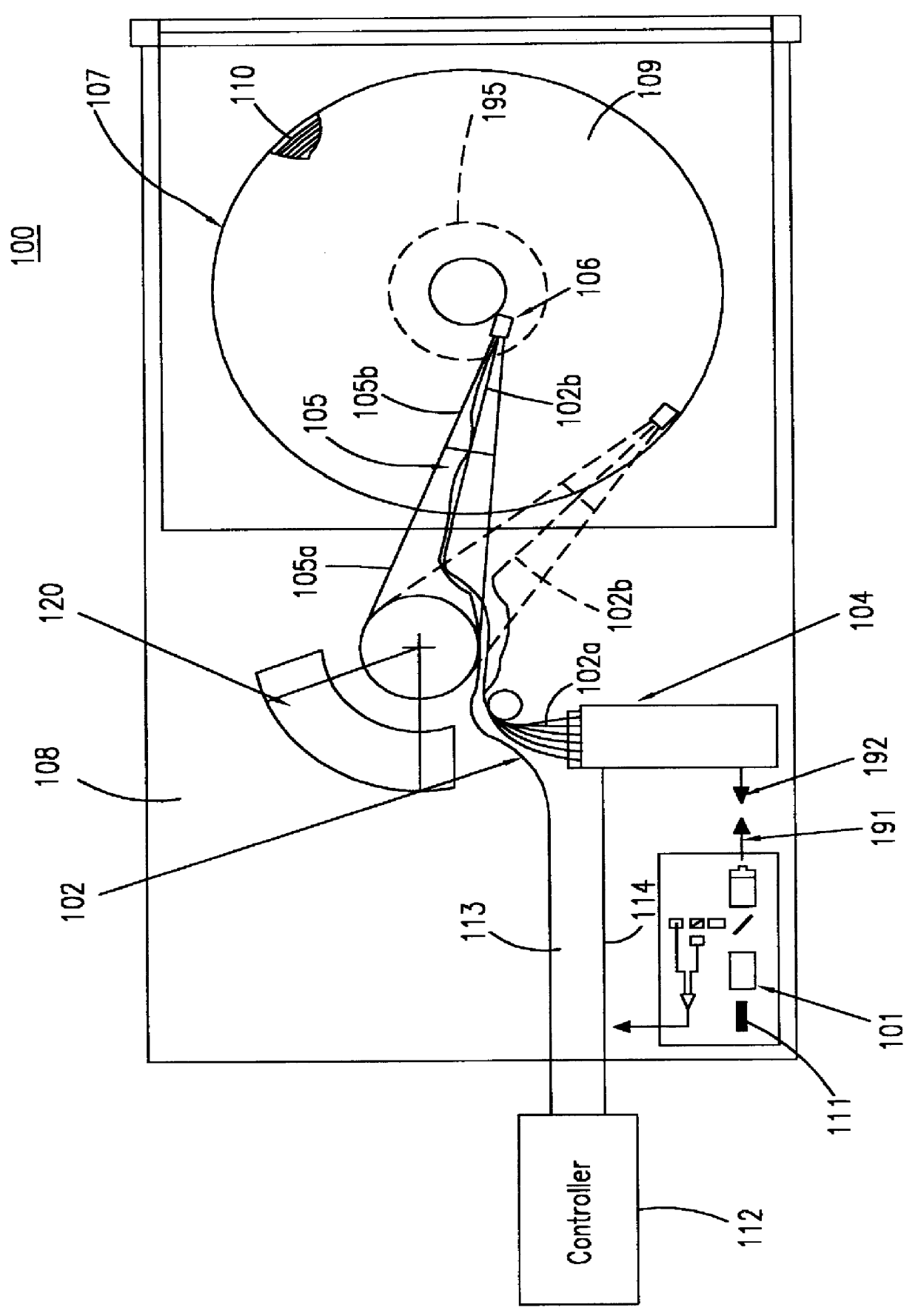
Referring in detail now to the drawings wherein similar parts of the invention are identified by like reference numerals, there is seen in FIG. 1 a diagram showing a magneto-optical data storage and retrieval system. In a preferred embodiment, magneto-optical (MO) data storage and retrieval system 100 includes a set of Winchester-type flying heads 106 that are adapted for use with a set of double-sided magneto-optical disks 107, one flying head for each MO disk surface. MO disks 107 are rotatably carried in a stack by a support body 108 and for simplicity only one of the disks 107 is shown in FIG. 1. In a preferred embodiment, a set of six disks 107 are provided in a stack. Each side of a disk 107 has a planar storage surface 109 provided with a plurality of concentrically disposed data tracks 110 thereon. For simplicity, only several of the data tracks 110 are shown in FIG. 1 and have been enlarged relative to the size of disk 107 for permitting visualization thereof.

The set of fly...


PUM


Abstract

A magneto-optical data storage system having a magneto-optical disk rotatably mounted on a support body. The disk has a planar storage surface with a plurality of concentrically disposed data tracks. A flying magneto-optical head is mounted on the distal extremity of an arm pivotably mounted on the support body for aerodynamic suspension adjacent the storage surface during rotation of the disk on the support body. A mirror assembly of micron dimensions is carried by the head for reflecting a laser beam between an optical light emitter and receiver carried by the arm and the storage surface of the disk to permit the optical recording and/or reading of information on the data tracks. The mirror assembly has a planar base and a planar mirror spaced apart from the planar base and disposed generally parallel to the planar base. The planar mirror has a longitudinal axis extending between first and second end portions. The mirror assembly further has first and second hinge members secured to the planar base extending along the longitudinal axis and connected to the first and second end portions. The mirror is rockable between first and second positions about the longitudinal axis relative to the planar base and at least a portion of the mirror is of a conductive material. The mirror assembly has first and second spaced-apart electrodes carried by the planar base for driving the mirror between the first and second positions.

Description

1. Field of the InventionThe present invention relates generally to data tracking, storage and retrieval systems and, more particularly, to data tracking, storage and retrieval systems that include steerable optics.2. Background ArtIn data recording and retrieval systems that use a moving media having a varying material characteristic, detectable variations from previously encoded media locations may be retrieved using reflected incident light. Such variations may also be used to provide servo control signals for following previously recorded data tracks. For example, in a magneto-optical storage system, using a magneto-optical (MO) recording material deposited on a rotating disk, information may be recorded on the disk as spatial variations of magnetic domains. During readout, the magnetic domain pattern modulates an optical polarization, and a detection system converts a resulting signal from optical to electronic format.In one type of magneto-optical storage system, a magneto-opt...

Claims


Application Information

Patent Timeline
IPC IPC(8): G02B26/08G11B7/22G11B11/105G11B11/00G11B7/085
CPCB82Y30/00G02B26/0816G11B7/08564G11B11/1058G11B11/10576G11B7/22G11B11/10554
Inventor DRAKE, JOSEPH D.JERMAN, JOHN H.
Owner SEAGATE TECH LLC
Why Eureka
Try Eureka