Method and apparatus for acoustic logging of fluid density and wet cement plugs in boreholes

a technology which is applied in the field of acoustic logging of fluid density and wet cement abandonment plugs in boreholes, oil and gas well (borehole) logging tools, etc., can solve the problems of inability to transfer acoustic energy, the ability of the ultrasonic transducer to lose the acoustic coupling, and the prior-art method cannot be used to measure the properties of heavy drill fluids, oil

Inactive Publication Date: 2000-04-18
WEATHERFORD CANADA PARTNERSHIP +1
View PDF6 Cites 61 Cited by
  • Summary
  • Abstract
  • Description
  • Claims
  • Application Information

AI Technical Summary

Problems solved by technology

If the total weight of fluid within the borehole decreases too much, it can lead to a blowout when a high-pressure zone is entered.
One problem encountered with the foregoing approach is that an ultrasonic transducer can lose the acoustic coupling, that is, the ability to transfer the acoustic energy, when in poor contact with the body of the tool, which is typically built of a metal material such as steel.
Another problem encountered in such prior art fluid density measurement techniques is that, during the measurement of the velocity of sound in the fluid, the signal must pass through two solid / fluid and fluid / solid interface-transmissions, plus one fluid / solid interface-reflection.
The foregoing prior-art method clearly cannot be used to measure the properties of heavy drill fluids, oil-based drill fluids, or wet cement abandonment plugs, where the signal attenuation at ultrasonic frequencies is very high, well above 20 dB / inch attenuation rate.
Prior art techniques for locating and determining the quality of downhole wet cement abandonment plugs, such as that described in U.S. Pat. No. 5,036,916, do not, however, locate both the top and bottom of the cement plug.
That method in particular is invasive (taking a sample of the cement for further analysis at the surface), and very time-consuming in operating the sample chamber to draw cement into the chamber, costing rig time, and incurring the associated risk and expense.

Method used


Image

  • Method and apparatus for acoustic logging of fluid density and wet cement plugs in boreholes
  • Method and apparatus for acoustic logging of fluid density and wet cement plugs in boreholes
  • Method and apparatus for acoustic logging of fluid density and wet cement plugs in boreholes

Examples


Embodiment Construction

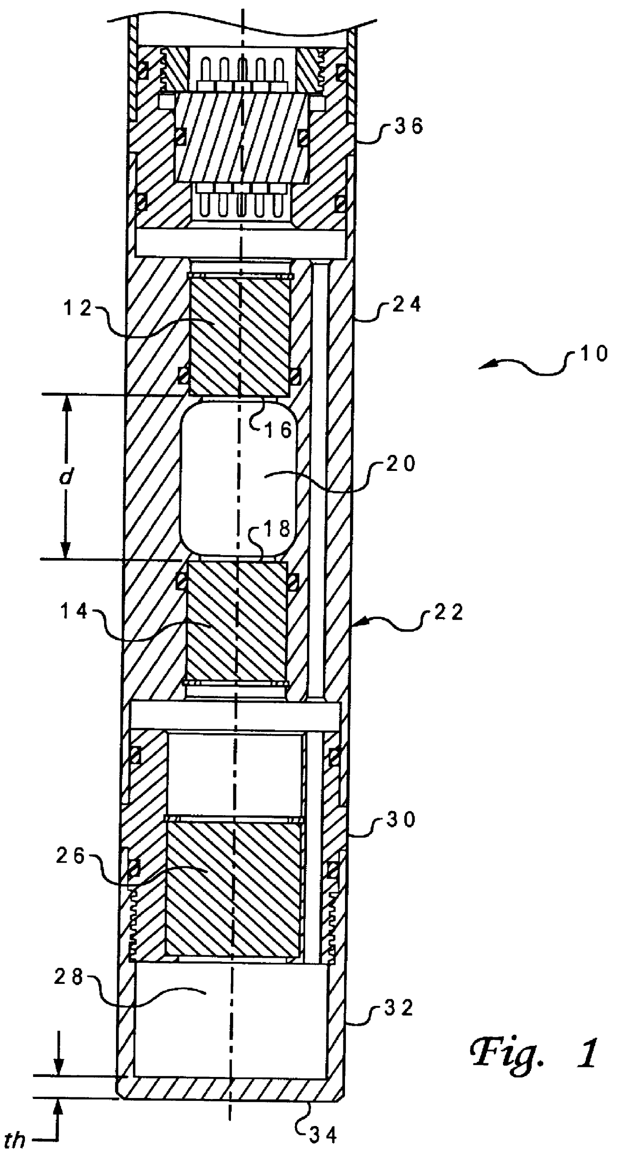
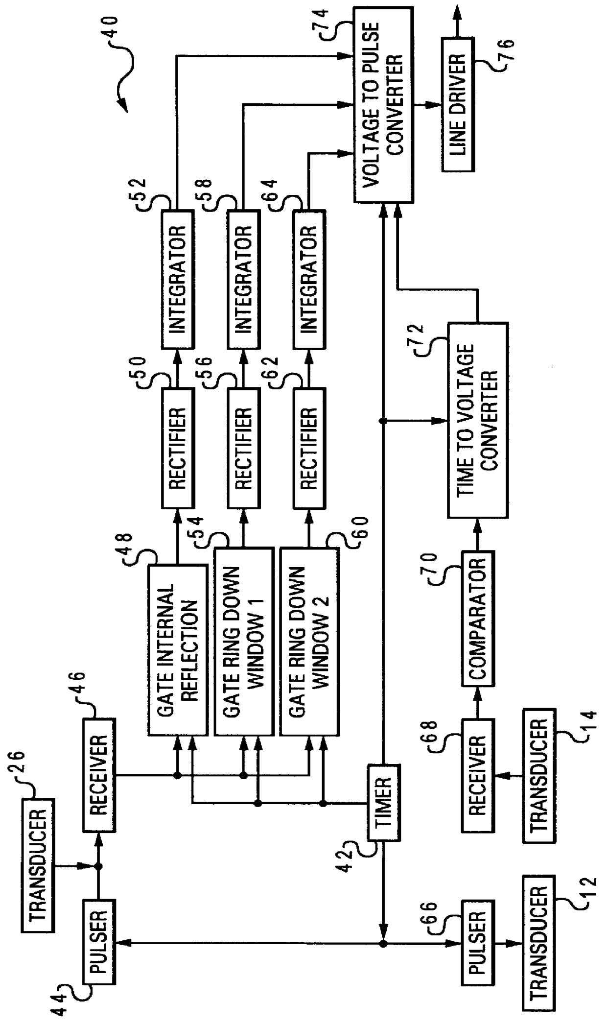
With reference now to the figures, and in particular with reference to FIG. 1, there is depicted one embodiment 10 of an acoustic logging tool constructed in accordance with the present invention. Acoustic logging tool 10 is elongated and sized to travel within a borehole, and is shown in a cross-section passing through (parallel to) the longitudinal axis of the tool. As those skilled in the art will appreciate, tool 10 may be incorporated into a drill collar for downhole applications.

Tool 10 may be used to determine fluid density by measuring the acoustic impedance and the sonic velocity of fluids in a borehole. Tool 10 is generally comprised of a pair of ultrasonic transducers, 12 and 14, disposed with their respective transmitting active surfaces 16 and 18 substantially parallel to each other, and both directly exposed to an opening 20 where drilling fluid, borehole fluid, or wet cement can easily flow in and out as the tool travels along a borehole. Tool 10 includes an elongated...


PUM

PropertyMeasurementUnit
densityaaaaaaaaaa
densityaaaaaaaaaa
thicknessaaaaaaaaaa

Abstract

A method of determining the acoustic impedance of a fluid in a borehole, by gating a reflected acoustic signal into a plurality of time slots, and comparing received energies of the signal for the time slots to obtain a value indicative of the acoustic impedance of the fluid. The value may be normalized to yield the acoustic impedance of the fluid using the acoustic impedance of, e.g., water as a calibration point. The comparison is performed by comparing a ratio of an integration of a first ring down time slot and a second ring down time slot, to an integration of an internal reflection time slot. The acoustic pulse may be generated using a transducer immersed in an intermediate fluid contained within a chamber defined in part by a plate in contact with the borehole fluid and having a thickness such that a mechanical resonance frequency of the plate in a thickness mode is substantially equal to a resonance frequency of the transducer. The sonic velocity of the fluid is also measured and, when combined with the acoustic impedance, is used to determine the fluid density.

Description

1. Field of the InventionThe present invention generally relates to devices for measuring fluid properties, and also generally relates to oil and gas well (borehole) logging tools. More particularly, the invention relates to an improved method and apparatus for determining the density of drilling fluid by measuring the acoustic impedance and the sonic velocity of the fluid in a borehole. The same method and apparatus can be used to locate and determine the quality of a downhole wet cement abandonment plug positioned in a borehole.2. Description of Related ArtIn various industrial processes that involve fluid material, it is useful to know the properties of the fluids involved. These fluid properties include, for example, density, compressibility, reflectance, acoustic impedance, viscosity and attenuation. Knowledge of the values of these various properties can be used to adjust process parameters or warn of impending calamity. In many applications, such as oil and gas well (borehole...

Claims


Application Information

Patent Timeline
Patent Type & Authority Patents(United States)
IPC IPC(8): E21B21/08E21B49/00E21B21/00E21B47/00G01N29/02G01N29/032G01N29/34G01N29/22G01N29/36G01N29/38G01V1/44G01V1/40E21B47/10
CPCE21B21/08E21B47/0005E21B47/101E21B49/005G01N29/032G01N29/225G01V1/44G01N29/38G01N29/348G01N2291/011G01N2291/018G01N2291/022G01N2291/02818E21B47/005E21B47/107
Inventor TELLO, LUCIO NELSONBLANKINSHIP, THOMAS JAYROBERTS, EDWIN KAMM
Owner WEATHERFORD CANADA PARTNERSHIP
Why Eureka
Try Eureka