Distributed type fiber optic sensor based on optical fiber cavity attenuation and vibration technique

A distributed optical fiber and optical fiber splitter technology, which is applied in the direction of using optical devices to transmit sensing components, optical waveguide coupling, etc., can solve problems such as processing difficulties, limiting the range of laser wavelengths, and inability to meet distributed sensing requirements. , to achieve the effect of high measurement accuracy, fast measurement speed and easy expansion

Inactive Publication Date: 2008-11-05
NORTHWESTERN POLYTECHNICAL UNIV
View PDF0 Cites 25 Cited by
  • Summary
  • Abstract
  • Description
  • Claims
  • Application Information

AI Technical Summary

Problems solved by technology

In 2002, in the paper "Cavity-enhanced spectroscopy in optical fibers" (Optics Letters, 2002, 27(21): 1878-1880), Gupta M et al. used a 10m-long single-mode optical fiber cavity with a highly reflective coating on the end face to carry out Research on medium refractive index sensing; in 2004, Tarsa P B et al. used a single-mode optical fiber cavity coated with a high-reflection film on the end face and used as a The bitapered optical fiber of the sensing element has been resear...

Method used


Image

  • Distributed type fiber optic sensor based on optical fiber cavity attenuation and vibration technique
  • Distributed type fiber optic sensor based on optical fiber cavity attenuation and vibration technique
  • Distributed type fiber optic sensor based on optical fiber cavity attenuation and vibration technique

Examples


Embodiment Construction

[0026] The present invention will be further described now in conjunction with accompanying drawing:

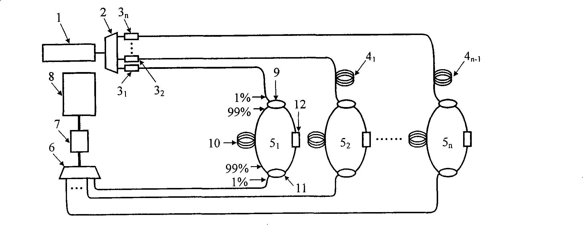
[0027] Device embodiment 1, such as figure 1 As shown, the present embodiment takes n=4, and the measuring device of the present invention includes: a pulsed laser light source 1, an optical fiber splitter 2, and an adjustable optical attenuator 3 1 、3 2 、3 3 、3 4 , fiber optic delay line 4 1 、4 2 、4 3 , Fiber Ring 5 1 、5 2 、5 3 、5 4 , fiber combiner 6, high-speed photodetector 7, high-speed A / D conversion and signal processing module 8. Fiber ring 5 1 It includes two 1×2 optical fiber couplers 9 and 11 with a splitting ratio of 99%:1%, a single-mode optical fiber 10 and an optical fiber sensing element 12 . The two ends of the single-mode optical fiber 10 are respectively fused with 99% of the two ports of the two optical fiber couplers 9 and 11, and the optical fiber sensing element 12 is respectively connected to the two ports of the two optical fiber couplers ...


PUM


Abstract

The invention relates to a distributing optical fiber sensor based on the fiber cavity ring-down technology, characterized in that, a laser outical source is connected with an optical fiber spliter connected with a plurality of adjustable optical attenuators; a first optical fiber ring is connected with an adjustable optical attenuator, and the other optical fiber rings are connected with the corresponding adjustable optical attenuators through the revelent optical fiber delay line; a plurality of output ends of the optical fiber ring are connected with the optical fiber combiner which is connected with a high speed photodetector, a high speed A/D conversion and signal process module in turn; the optical fiber ring is respectively connected with an optical fiber coupler at the upper and lower two ends of the ring optical fiber, while the left side and he right side are respectively connected with a single-mode fiber optical fiber and an optical fiber sensing elements. The invention has the beneficial effect that, the measurement of the intensity or the wavelength is converted to that of the optical fiber ring ring-down time, which realizes the one time of measurement is just the millisecond magnitude with simple demodulation method, and easily realizes the distributing optical fiber sensor to measure a plurality of physical quantity at the same time.

Description

technical field [0001] The invention relates to a distributed optical fiber sensor based on optical fiber cavity ring down technology, belongs to the field of optical fiber sensors, and relates to a design of a distributed optical fiber sensor and a demodulation method thereof. Background technique [0002] Optical fiber sensing technology is a new type of sensing technology that uses light as the carrier and optical fiber as the medium to perceive and transmit external signals, which developed rapidly with the development of optical fiber and optical fiber communication technology in the 1970s. Compared with traditional mechanical and electronic sensors, fiber optic sensors have the following advantages: (1) high sensitivity and large dynamic range; (2) anti-electromagnetic interference, good electrical insulation, corrosion resistance, and can be used at high temperature and high pressure (3) The sensor head has a simple structure, small size, light weight, and is suitable...

Claims


Application Information

Patent Timeline
IPC IPC(8): G01D5/353G02B6/26
Inventor 杨德兴姜亚军赵建林张毓灵
Owner NORTHWESTERN POLYTECHNICAL UNIV
Why Eureka
Try Eureka