Optical loop ring-down

a technology of optical loops and rings, applied in the field of optical loop ringdown, can solve the problems of difficult measurement of low optical losses using such techniques, unreliable data, and limited sensitivity of single or multi-pass absorption techniques, and achieve the effect of illumination of loops

Inactive Publication Date: 2005-01-11
QUEENS UNIV OF KINGSTON
View PDF6 Cites 23 Cited by
  • Summary
  • Abstract
  • Description
  • Claims
  • Application Information

AI Technical Summary

Problems solved by technology

In particular, the sensitivity of the single or multipass absorption techniques is limited by the pathlengths that can be achieved, the sensitivity of the detector towards small changes in transmission, and the temporal and spatial stability of the signal, which in turn is influenced by the temporal and spatial stability of the light source and of the reference vs. signal channel, the alignment of the source, the medium and detector, and of the detector and associated equipment.
As a result, measurement of low optical losses using such technique is difficult and yields unreliable data.
Although cavity ring-down spectroscopy (CRDS) is well established as a gas phase method, applications in condensed phase have, until recently, been limited to absorption measurements of films through evanescent field experiments on the surface of all-solid state cavities (Pipino et al.
(2001) inserted a gas phase absorption cell into a fiber-loop, leading to very high transmission losses.

Method used


Image

  • Optical loop ring-down
  • Optical loop ring-down
  • Optical loop ring-down

Examples


working examples

Example 1

Fiber Loop Ring-Down Spectroscopy

Introduction

The characterization of optical properties, such as transmission spectrum or typical dB loss per unit length, of optical fibers is of central importance to any industry that uses or manufactures these fibers. Frequently, these properties are determined using a long length of fiber and measuring, e.g., the transmission spectrum, using a well calibrated and stable light source and detector. Measuring the optical properties and typical losses of fiber connections (fusion splices or mechanical splices) is more difficult since an individual splice ideally does not contribute much to the overall loss and therefore the measurement will frequently only give an upper limit for the loss. Alternatively, one can determine the average loss of a connection using are large number of splices, but will not be able to characterize the distribution of losses of those connections easily.

The fiber loop ring-down technique of the invention can be used...

example 2

A Ring-Down Absorption Detector for a Laboratory-on-a-Chip Device

Introduction

Recent developments in the area of micro-Total Analysis Systems (μ-TAS) have included systems that perform chemical reactions, separation and detection on a single microchip (Harrison et al. 1993; van den Berg et al. 2000). Compared to conventional systems, lab-on-a-chip devices have reduced analysis times and use minute amounts of sample, solvents and reagents due to their small dimensions. In fact, the analysis of a simple mixture has been performed in less than one millisecond using only 100 picoliters of sample (Jacobson et al. 1998). The small amounts of sample and reagent required, combined with rapid analyses, make microfluidic devices extremely attractive for several analytical applications including chemical analysis of biological and medicinal samples.

Currently, most microfluidic analyses utilize molecular fluorescence as a means of detection. However, fluorescence is not a universal method of det...

example 3

A Ring-Down Absorption Detector

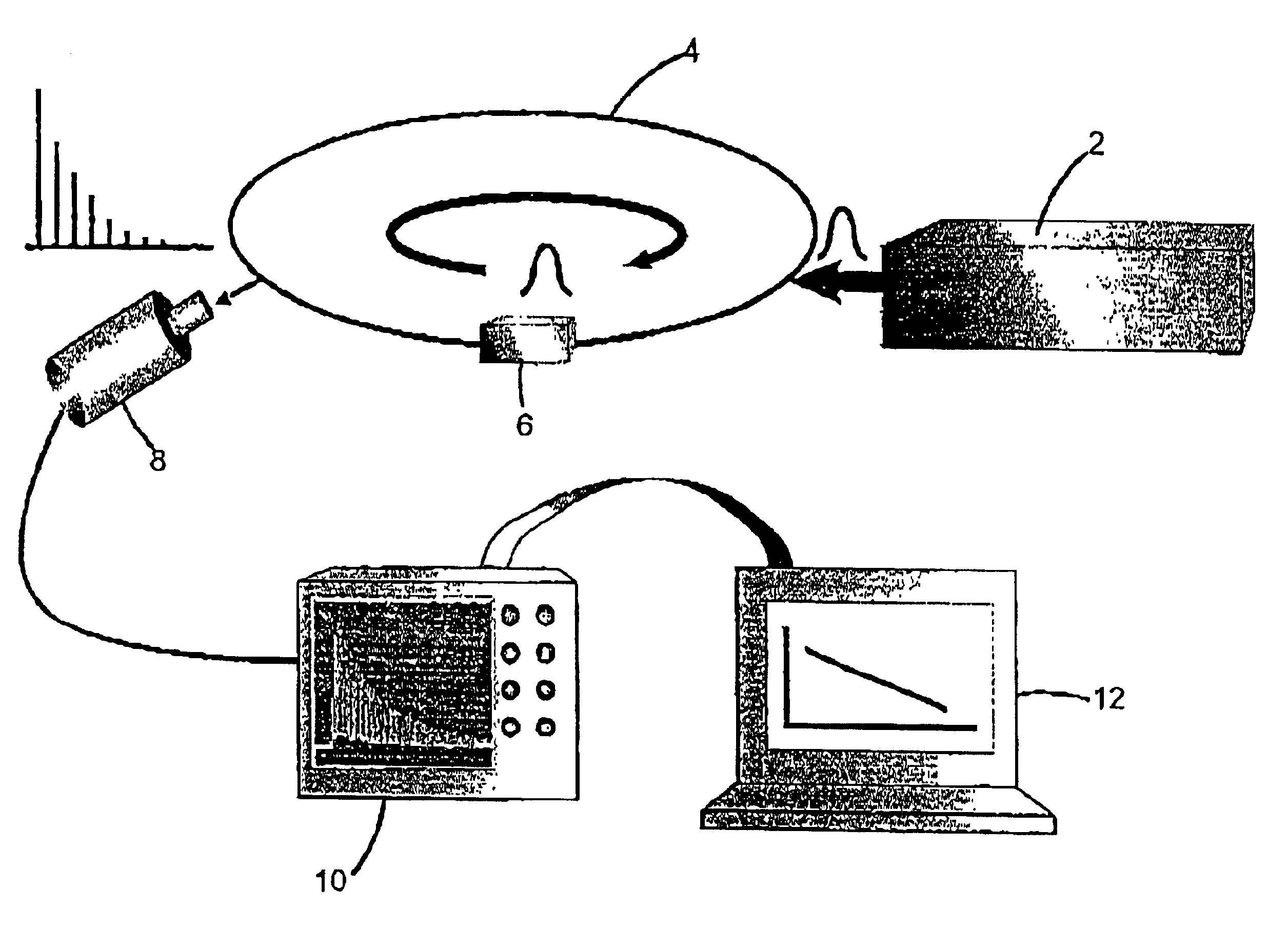
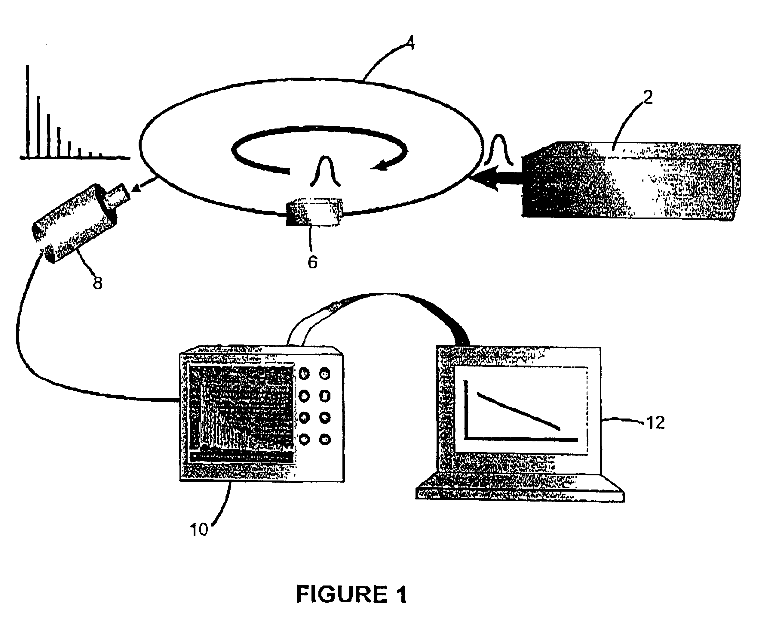
An experimental setup as shown in FIG. 1 was used. The light source was a nitrogen (or Nd:YAG) laser-pumped dye laser with a bandwidth of about 2 nm, a pulse width of 500 ps (or 7 ns) and a power of 50-200 μJ. The mildly focussed output of this laser was coupled into an optical fiber loop (length 1 m-77 m) at a 3 cm radius bend of the fiber (multimode Anhydroguide-G LOW OH Vis-IR Fiber, Fiberguide Industries, 50 μm core, 125 μm cladding). The loop was completed using a splice connector (Fibrlok®, 3M). A photomultiplier tube (PMT) (Hamamatsu, R955) was located at a distance (minimum=50 cm) away from the excitation region and monitored the emitted light at a similar 3 cm radius bend of the fiber. The PMT was gated such that the first 270 ns after each laser pulse were not recorded. This was done because the initial photon signal had abnormally high intensity, probably resulting from stray light and light coupled into the jacket of the fiber as opposed to...


PUM

PropertyMeasurementUnit
average path lengthaaaaaaaaaa
lengthaaaaaaaaaa
lengthaaaaaaaaaa

Abstract

The invention provides a method and apparatus for measuring one or more optical properties of a test medium, comprising providing an optical waveguide loop comprising a test medium, illuminating the optical waveguide loop with a plurality of light pulses, and detecting roundtrips of the light pulses at one or more locations along the loop, wherein the detected light pulses are indicative of one or more optical properties of the test medium. Preferably, ring-down time of said light pulses is determined. The invention provides measures of optical properties such as absorbance and refractive index of a test medium such as a gas, a liquid, and a solid material.

Description

FIELD OF THE INVENTIONThis invention relates to methods and apparatus for measuring optical characteristics of a test medium or media. In particular, the invention relates to use of ring-down time of light in an optical loop to measure optical characteristics of a test medium or media.BACKGROUND OF THE INVENTIONMeasurement of low optical losses in an absorbing medium is commonly performed by applying a light signal to a long absorbance path length, using single-pass or multi-pass paths in the absorbing medium. The signal is measured as a function of the desired parameter, such as wavelength of the light, time, concentration, etc., by a light detector, in comparison with a reference channel. Such a light detector normally terminates the light path of the signal and the reference channel. These measurements require either light sources with very low variations in intensity or a good reference scheme. In particular, the sensitivity of the single or multipass absorption techniques is li...

Claims


Application Information

Patent Timeline
Patent Type & Authority Patents(United States)
IPC IPC(8): G01N21/31G01N21/39G01N21/41G01M11/02H04B10/08
CPCG01N21/41G01N21/39
Inventor LOOCK, HANS-PETERBROWN, R. STEPHENKOZIN, IGORTONG, ZHAOGUOOLESCHUK, RICHARD D.
Owner QUEENS UNIV OF KINGSTON
Why Eureka
Try Eureka