Continuously variable gear transmission

a transmission device and continuous variable technology, applied in the direction of gearing, mechanical equipment, hoisting equipment, etc., can solve the problems of inconvenient replacement, significant torque limitations, belts or other components in frictional engagement can be subject to wear, etc., to improve efficiency and reliability, increase torque, and reduce running costs

Inactive Publication Date: 2000-05-23
YUN YOWANG
View PDF7 Cites 5 Cited by
  • Summary
  • Abstract
  • Description
  • Claims
  • Application Information

AI Technical Summary

Benefits of technology

An additional object of the invention is to provide a continuously variable gear transmission which provides improved efficiency and reliability, increased torque, reducing running costs and increasing service intervals.
According to one aspect of the invention, a continuously variable, gear transmission comprises a drive gear and a driven gear on respective shafts; one of the drive gear and driven gear having a continuous axial taper providing an axially varying pitch diameter, another of the drive gear and driven gear having teeth mounted for relative movement about a shaft axis; means for continuously varying a relative axial position of engagement of the gears so as to vary the effective pitch diameter of the said one gear; and, means for moving teeth of said another gear relatively to continuously vary an effective circular pitch of selected teeth thereof to match a circular pitch of the teeth of said one gear for ensuring meshing engagement throughout the varying axial positions, whereby the velocity ratio of the transmission is varied continuously.

Problems solved by technology

One well known friction type, employs cooperating friction belts and pulleys of varying diameter while another involves cooperation between drive / driven shafts and bodies of continuously varying shape such as cones but the reliance on friction imposes significant limitations on torque while the friction belts or other components in frictional engagement can be subject to wear, requiring inconveniently frequent replacement, increasing the operating costs.
However, the prior proposal does not follow the laws of gearing.
In consequence, it is believed that, in practice, a substantial amount of sliding friction will occur between the sprung teeth and the pinion teeth resulting in relatively rapid wear and energy losses.
Other prior approaches involving gears, such as epicyclic arrangements utilizing one-way clutches have resulted in a variable velocity output and relatively low reliability.
Furthermore, engine braking is usually not possible.
Another, so-called frictionless approach, taught by U.S. Pat. Nos. 4,817,464 and 4,850,248 issued to Korban et al in 1989 has the disadvantage that the output is not of constant velocity.

Method used


Image

  • Continuously variable gear transmission
  • Continuously variable gear transmission
  • Continuously variable gear transmission

Examples


Embodiment Construction

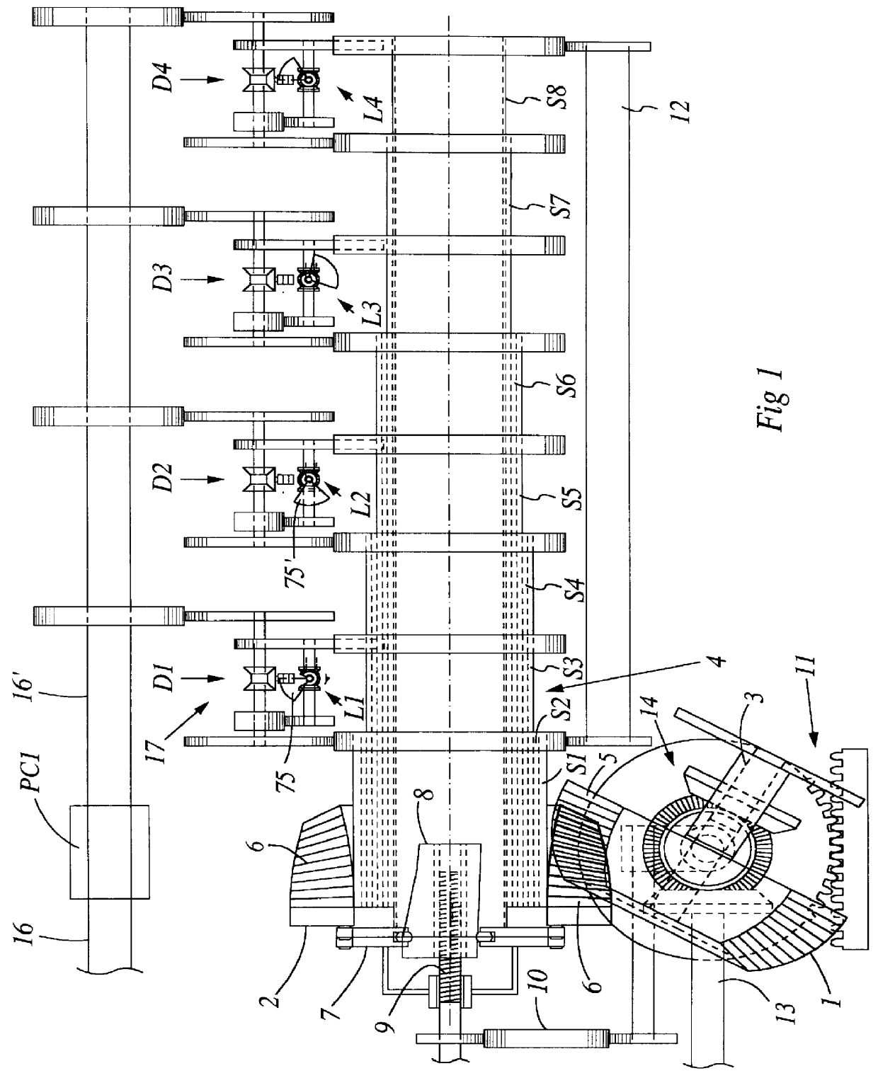
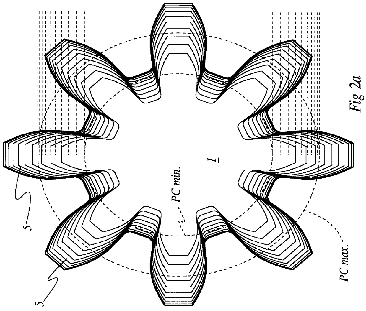
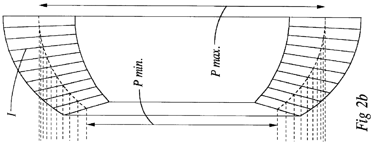
Briefly described, with reference to FIG. 1, the continuously variable gear transmission comprises drive and driven gears 1 and 2, respectively, having respective, coplanar, intersecting shaft and shaft assembly 3 and 4, with respective teeth 5 and 6, in meshing engagement. The drive gear 1 has a dome shape profile, having a continuous axial taper and fixed teeth providing an axially varying effective pitch diameter, whereas the teeth 6 of the driven gear 2 are relatively movable to vary the effective circular pitch, being connected by linkage 7 for relative (circumferential) movement (in the direction of gear rotation) by following an axially varying, eccentric profile of a pitch control drum 8, axially positionable by a lead screw 9. (Alternative embodiments could comprise rack and pinion or other type of mechanisms, for example, for effecting drum movement).

A carriage driven rack and pinion mechanism 11 reciprocates the drive gear 1 axially while varying the angle of intersection...


PUM


Abstract

A continuously variable gear transmission has a hemispherical drive gear providing an axially varying pitch diameter and an axially varying effective circular pitch, and a driven gear with a constant pitch diameter having teeth tapering axially in an opposite sense to the axially varying effective circular pitch of the drive gear. A pitch control drum guides teeth of the driven gear relatively around the shaft axis to continuously vary their effective circular pitch to match a circular pitch of the teeth of the drive gear for ensuring meshing engagement throughout the varying axial positions, whereby the velocity ratio of the transmission is varied continuously. The control drum has a guiding surface extending therearound with an axially tapering, conical guiding portion providing an arcuate guiding surface portion of constant transverse and continuously axially varying radius. An interconnected rod assembly links the adjacent movable teeth together for movement as a ring around the guiding surface of the drum so that the effective circular pitch of the teeth engaging the drive gear is determined by the radius of the guiding portion and so that a tooth engaging the drive gear has a constant angular velocity throughout such engagement, The shaft of the driven gear comprises a plurality of coaxial sub-shafts carrying respective individual teeth mounted coaxially with the drum. A mechanism continuously and simultaneously varies both an angle of intersection of the drive and driven gear shafts, bringing different circumferential locations of the drive gear having different pitch diameters into engagement with the driven gear, and a relative axial position of engagement of the gears, changing a circular pitch of the driven gear to match a circular pitch of the drive gear. A differential connects the selected teeth of the driven gear gear to a power output only when the teeth are at the constant angular velocity.

Description

FIELD OF THE INVENTIONThe invention relates to a continuously variable gear transmission.BACKGROUND OF THE INVENTIONThere have been many prior attempts over many years to provide practical continuously variable transmissions.One well known friction type, employs cooperating friction belts and pulleys of varying diameter while another involves cooperation between drive / driven shafts and bodies of continuously varying shape such as cones but the reliance on friction imposes significant limitations on torque while the friction belts or other components in frictional engagement can be subject to wear, requiring inconveniently frequent replacement, increasing the operating costs.Another approach taught by WO9302302 published in 1993, teaches engagement between a conical pinion and a "hedgehog" wheel with spring loaded teeth which retract and emerge from recesses to accommodate pinion taper as the wheel is displaced along an inclined axis to maintain it in mesh with the conical pinion.How...

Claims


Application Information

Patent Timeline
Patent Type & Authority Patents(United States)
IPC IPC(8): F16H3/42F16H3/02
CPCF16H3/42Y10T74/1966Y10T74/19949
Inventor YUN, YOWANG
Owner YUN YOWANG
Why Eureka
Try Eureka