Combustion system

a combustion system and combustion technology, applied in the field of combustion systems, can solve the problems of increasing environmental pollutants, difficulty in obtaining these fuels, and increasing the price of such fuels

Inactive Publication Date: 2000-05-30
JAASMA DENNIS R
View PDF15 Cites 25 Cited by
  • Summary
  • Abstract
  • Description
  • Claims
  • Application Information

AI Technical Summary

Problems solved by technology

This was partly due to the decrease in oil and gas supplies at that time making it quite difficult to obtain these fuels and the simultaneous extreme price increases in such fuels.
However, with the steady increase of residential and commercial solid fuel combustion came a steady increase in environmental pollutants, such as copious amounts of particulate matter.
However, after many years of field measurements, the field performance of the EPA certified wood burning stoves leaves much room for improvement.
Consumer misuse and / or inattention to proper operation, physical degradation of critical components and lack of maintenance, amongst other reasons, cause emissions to be greater than they need be.
The poor field performance of many wood burning stoves is further attributed to the fact that the wood burning stoves are designed to burn clean when burning the wood of the certification test, but are generally not as effective when burning cordwood or other solid fuels at a wider range of moisture contents.

Method used


Image

  • Combustion system
  • Combustion system
  • Combustion system

Examples


Embodiment Construction

For illustrative purposes only a wood burning stove will be described. However, it is well understood that the combustion system of the present invention can be a coal burning stove or any other combustion system that uses solid fuels, either industrially or commercially or residentially. It is further understood that the dimensions of the combustion system, including length, width, shape and other variables and quantities specified herein may vary with the type of system contemplated. Therefore, numbers and dimensions specified herein are not to be construed as limitations on the scope of the present invention, but are meant to be merely illustrative of one particular application of the present invention.

THE COMBUSTION SYSTEM

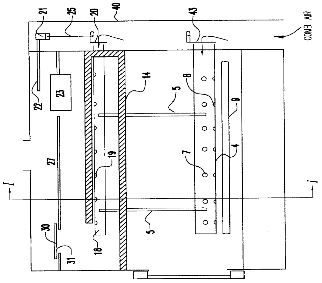
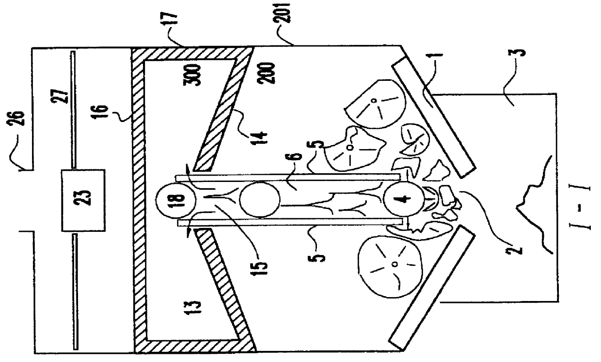
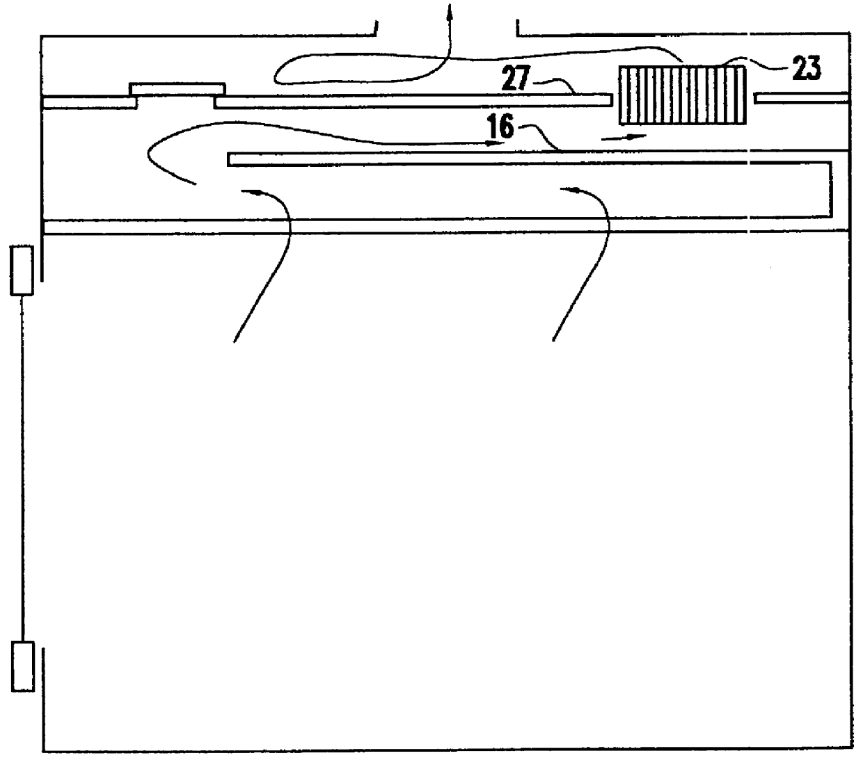
Referring now to the drawings, and more particularly to FIG. 1, there is shown a front sectional view of the combustion system comprising a primary combustion chamber 200 and a secondary combustion chamber 300 located substantially above the primary combustion ...


PUM


Abstract

A combustion system includes a primary combustion chamber divided into left and right sides by fuel-retaining standards defining a canyon or void extending into a secondary combustion chamber is provided. The floor of the primary combustion chamber and the fuel-retaining standards direct the burning solid fuel toward the lower part of the canyon, while at the same time retaining the non-burning solid fuel on either side of the fuel-retaining standards. The combustion system further includes an air delivery system having a lower air tube supplying high and low velocity air and an upper air tube. The lower air tube is positioned proximate to a firebox floor, while the upper air tube is positioned within the secondary chamber. Automatic air setting mechanisms are provided so that proper air settings can be maintained during various phases of a fire. The combustion system further includes a loading door having openings and a bypass system preventing the loading door from being fully closed unless the bypass is in the completely closed position. The secondary combustion chamber includes at least fuel protecting baffles and a secondary combustion chamber ceiling which extends partially over the entire length of the secondary combustion chamber or includes openings. A catalyst mounting system which minimizes canning and masking and a radiant catalyst heating system are also provided.

Description

1. Field of the InventionThe present invention generally relates to a combustion system for improved combustion of solid fuels and, more particularly, to a combustion system which prevents smothering and quenching of the solid fuels during burning while providing improved performance, such as, amongst others, reducing air borne pollutants.2. Background DescriptionResidential and commercial solid fuel combustion in the United States and around the world increased sharply after the oil embargoes of the 1970s. This was partly due to the decrease in oil and gas supplies at that time making it quite difficult to obtain these fuels and the simultaneous extreme price increases in such fuels. However, with the steady increase of residential and commercial solid fuel combustion came a steady increase in environmental pollutants, such as copious amounts of particulate matter. This increase in environmental pollutants was especially true with the increased usage of residential coal and wood bu...

Claims


Application Information

Patent Timeline
Patent Type & Authority Patents(United States)
IPC IPC(8): F24B5/02F24B1/00F23K3/06F24B5/00F23L9/00F23L9/02F23K3/00F23L9/04
CPCF23K3/06F23L9/02F24B5/026F24B1/006F23L9/04
Inventor JAASMA, DENNIS R.CHAMPION, MARK R.
Owner JAASMA DENNIS R
Why Eureka
Try Eureka