System for securing a support to an aircraft floor

a technology for aircraft floors and support posts, which is applied to aircraft floors, flexible elements, transportation items, etc., can solve the problems of wasting vertical loading space, reducing passenger comfort, and reducing the need for each container and pallet to be equipped with its own transport rollers secured to the underside of the platform or container bottom. , to achieve the effect of substantial flexibility

Inactive Publication Date: 2000-05-30
DAMELERKLESLER AVIATION
View PDF10 Cites 65 Cited by
  • Summary
  • Abstract
  • Description
  • Claims
  • Application Information

AI Technical Summary

Benefits of technology

Another advantage is seen in that existing containers and existing seat pallets can be used in the present system, whereby the present latching devices (2) of the seat pallets cooperate with the adapter (4). In the freight container embodiment any latching can be used. These characteristics of the invention provide a substantial flexibility for example with regard to the seat arrangements so that various customer wishes can be easily satisfied because the adapters (4, 13) can be placed anywhere along the stringers.

Problems solved by technology

For example, conventional pallets carrying passenger seats installed on a cabin floor in an aircraft reduce the initially available cabin height by about three inches which in turn reduces the passenger comfort.
The need for each container and each pallet to be equipped with its own transport rollers secured to the underside of the platform or container bottom is a disadvantage because these rollers or ball rollers take up vertical space.
Such a system wastes vertical loading space and therefore leaves room for improvement in reducing the vertical height that is required for moving pallets and / or freight containers along the floor.

Method used


Image

  • System for securing a support to an aircraft floor
  • System for securing a support to an aircraft floor
  • System for securing a support to an aircraft floor

Examples


Embodiment Construction

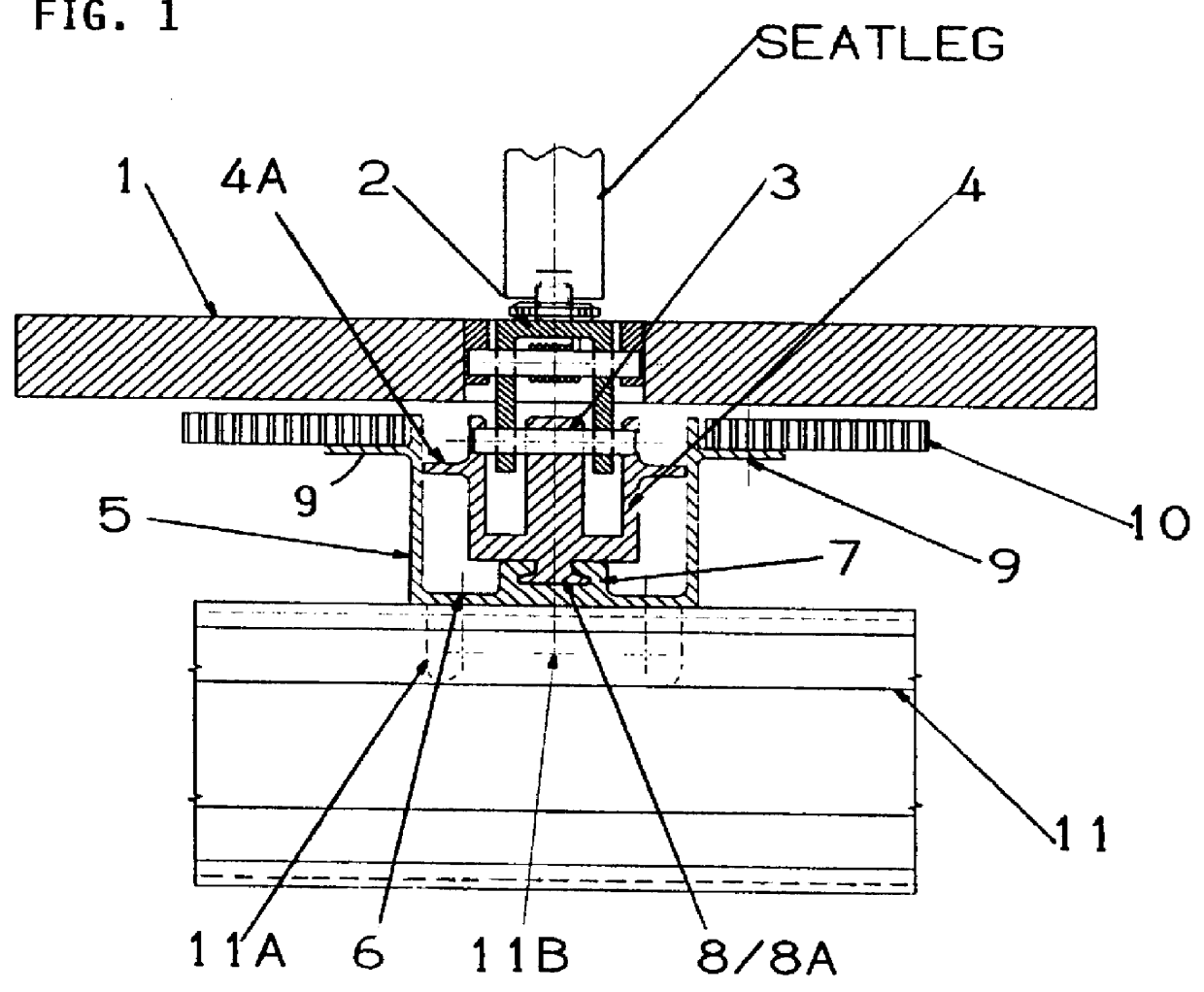
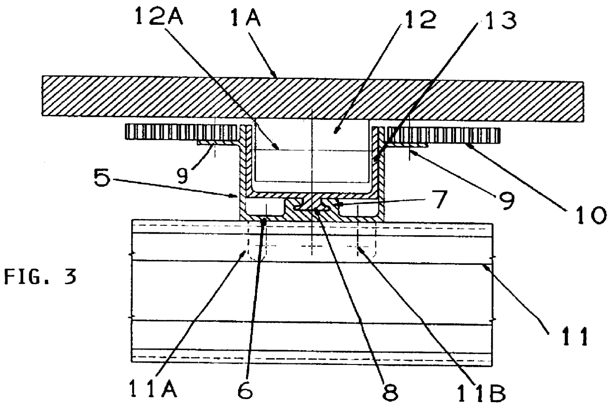
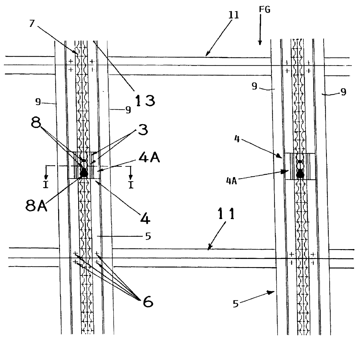
Referring first to FIGS. 1 to 4, a floor grid FG is formed of supporting cross-joists 11 and stringers 5 according to the invention extending in the direction of the longitudinal aircraft axis. The stringers 5 are secured to the cross-joists 11 by gusset brackets 11A and welding and / or screws or rivets 6, 11B. The joists 11 extend cross-wise to the longitudinal aircraft axis. Normally, the crossing angle between joists 11 and stringers 5 will be 90.degree., but the invention is not limited to that angle. Each stringer 5 has, according to the invention, a U-cross-sectional configuration forming a U-rail, as best seen in FIGS. 1 and 3, and faces with its open side upwardly. Each stringer 5 of the invention is equipped with a seat rail 7 having an interrupted crown for cooperation with interlocking members 8 / 8A. The seat rail 7 is provided either with a groove or with a tongue for the cooperation with the interlocking members 8 / 8A and / or with adapters 4, 13. Preferably, but not necessa...


PUM


Abstract

Supports such as a pallet carrying aircraft passenger seats or a bottom of a freight container are secured to a floor structure in an aircraft. For this purpose the floor structure includes floor stringers (5) supported on and secured to floor joists (11). The stringers (5) are U-rails having an upwardly open U-cross-section with a first interlocking member (8) in the U-cross-section. An adapter (4, 13) having a present existing stud (8) and shear pin system (8A) is secured in the U-rail of the stringers (5). The adapter (4) is secured to or securable to the support by a latching (2, 3). Another adapter (13) carries rotatable rollers or roller balls that project slightly above an upwardly facing floor level to permit, for example, freight containers or seat pallets to roll along the floor. Instead of adapter (13) it is also possible to install a present existing container latch carrier (14) in the present stringer (5).

Description

The invention relates to securing a support such as a pallet carrying passenger seats or the bottom of an LD freight container to the floor of an aircraft which can be the cabin floor or the loading floor.BACKGROUND INFORMATIONThe above mentioned supports in the form of pallets or the freight container bottoms are equipped with interlocking elements or latching devices for securing the supports to a floor in the aircraft. Where the floor is a loading floor, it is normally equipped with transport rollers or ball elements forming a floor surface on which freight container bottoms can be moved.Various freight latching system for securing pallets and containers to a floor in an aircraft are known in the art. Such systems include latching elements for securing the pallets or containers to the floor grid structure of the aircraft. Efforts have been made to reduce the weight of such systems and to minimize loss in vertical loading height above the respective floor. For example, conventiona...

Claims


Application Information

Patent Timeline
Patent Type & Authority Patents(United States)
IPC IPC(8): B64D9/00B60P7/08B60P7/13B64C1/20
CPCB64D9/00Y02T50/46Y02T50/40
Inventor KOOK, MANFREDSCHOPENHAUER, WOLFRAM
Owner DAMELERKLESLER AVIATION
Why Eureka
Try Eureka