Apparatus and method for displaying DPMS mode status using an OSD circuit

Inactive Publication Date: 2000-05-30
SAMSUNG ELECTRONICS CO LTD
View PDF8 Cites 53 Cited by
  • Summary
  • Abstract
  • Description
  • Claims
  • Application Information

AI Technical Summary

Problems solved by technology

This, however, would consume front panel space while increasing assembly costs and would necessitate that a user be well acquainted with specified states of the indicator or indicators through a guide (manual) provided by a display device manufacturer.
Meanwhile, if the signal cable (D-sub connector) for carrying video signals output by the main body of a personal computer to t

Method used


Image

  • Apparatus and method for displaying DPMS mode status using an OSD circuit
  • Apparatus and method for displaying DPMS mode status using an OSD circuit
  • Apparatus and method for displaying DPMS mode status using an OSD circuit

Examples


Embodiment Construction

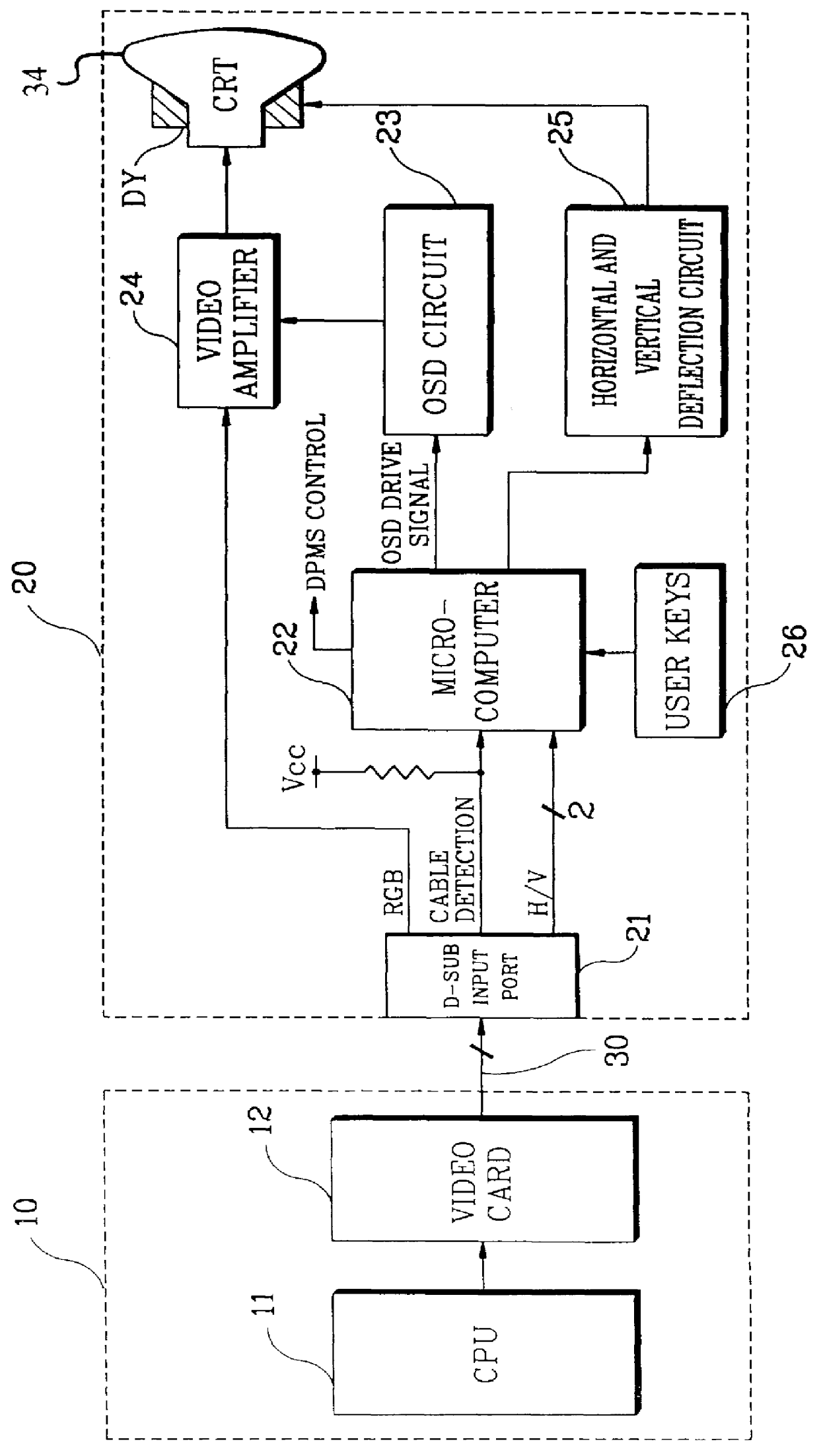
Referring to FIG. 1, data processed by a CPU 11 of a main body 10 of a personal computer system is converted to an RGB video signal by a video card 12. The video card 12 also generates a horizontal sync signal (H) and a vertical sync signal (V) for synchronizing the displayed video signal. The RGB video signal and the sync signals output from the video card 12 are transmitted to a D-sub input port 21 of a display device 20 via a signal cable 30. The RGB video signal transmitted to the D-sub input port 21 is output to a video pre-amplifier 24 for amplification. The amplified video signal is then applied to a CRT 34 under the control of a horizontal and vertical deflection circuit 25 in accordance with sawtooth waveforms respectively output to a pair of deflection yokes (DY).

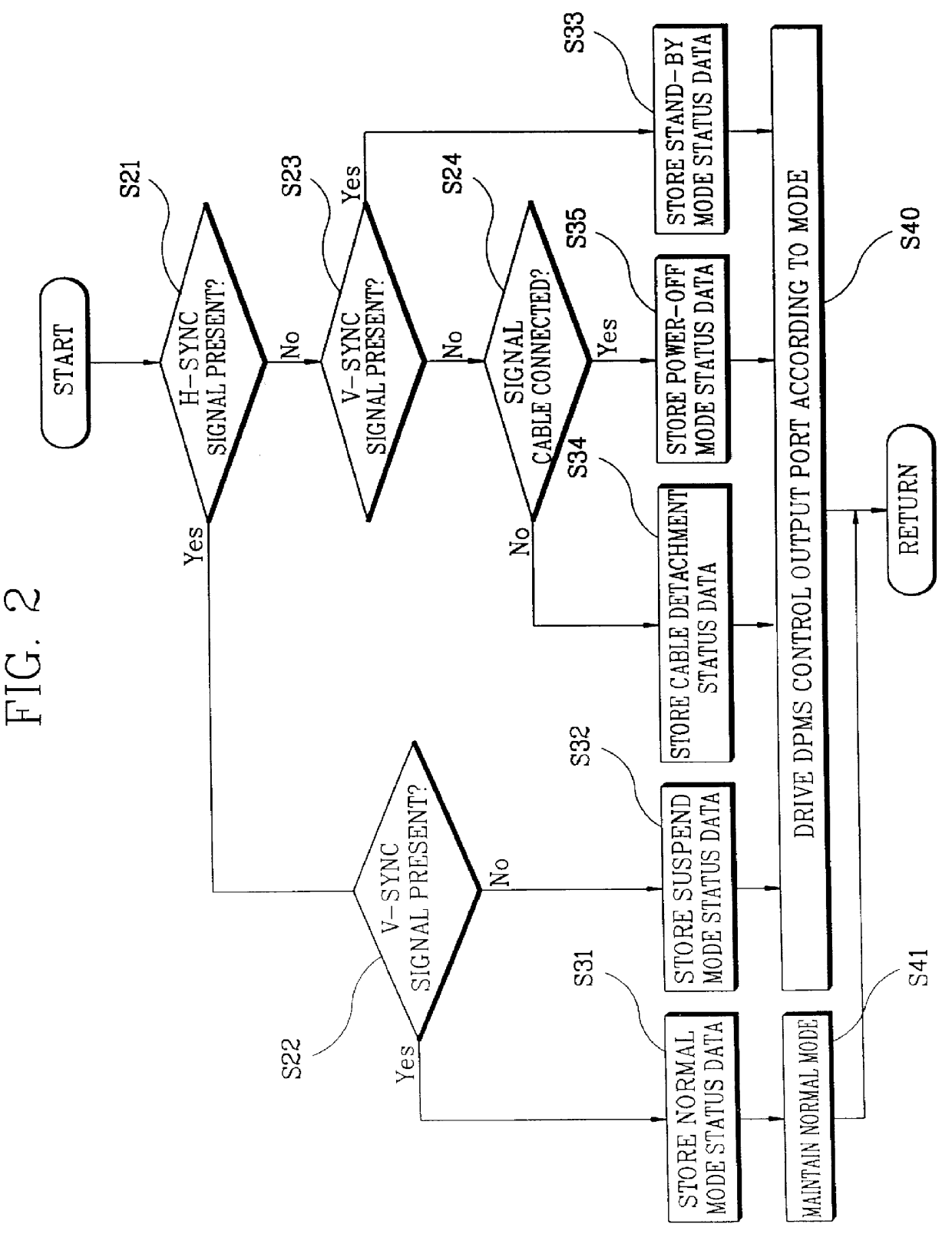
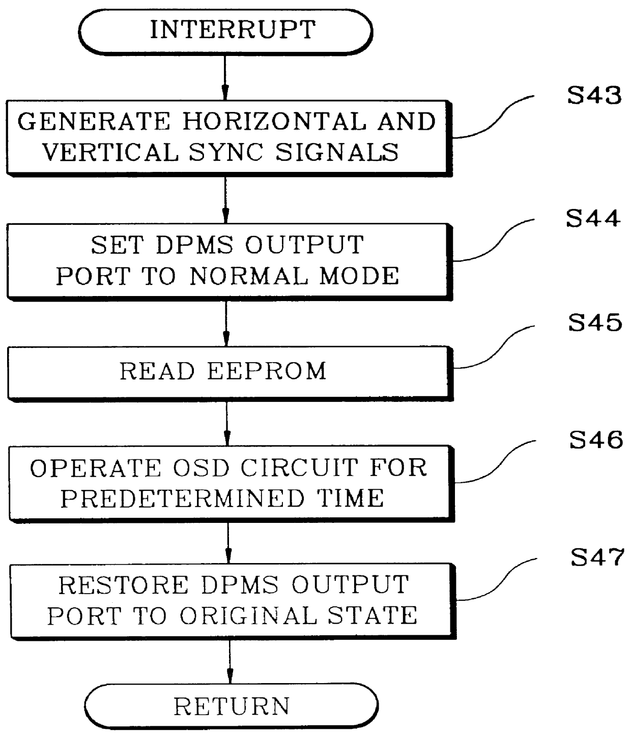
A microcomputer 22 comprises an internal memory (not shown), such as an EEPROM, which stores information regarding the status of the display device 20. More specifically, the microcomputer 22 stores a current DPMS...


PUM


Abstract

An apparatus and method for displaying the status of a current display power management signaling (DPMS) mode in a display device uses an on-screen display (OSD) circuit. The current DPMS mode is determined based on an input status of video sync signals and the connection of a signal cable. The current DPMS mode status data is stored in an internal memory of a microcomputer. The OSD circuit is driven using an OSD drive signal output from the microcomputer, so that a message indicative of the stored status data can be momentarily displayed on the display device. In a DPMS mode, any front panel key acts as a program interrupt for DPMS mode operation, which, upon activation, initiates a sequence whereby the DPMS mode is set to normal, horizontal and vertical sync signals are generated, the stored DPMS mode status data is read, and an OSD drive signal is generated. After a time sufficient for user recognition of the current DPMS mode, the OSD drive signal is discontinued and the DPMS mode is reset.

Description

CLAIM OF PRIORITYThis application makes reference to, incorporates the same herein, and claims all benefits accruing under 35 U.S.C. .sctn. 119 from my application entitled Display Power Management Signaling Display Method Using On-Screen Display in Display Device filed with the Korean Industrial Property Office on Feb. 24, 1997, and there duly assigned Ser. No. 97-5492 by that Office.1. Field of the InventionThe present invention relates to display devices and, more particularly, to a method for displaying the current status of a display device adopting a display power management signaling (DPMS) standard, and an apparatus for achieving the same, which enables DPMS mode verification using an on-screen display (OSD) circuit.2. Discussion of Related ArtA display device for use with a personal computer is generally manufactured with internal control means for reducing power consumption, such as the DPMS standard. In conformity with the DPMS standard, the host computer, which typically...

Claims


Application Information

Patent Timeline
IPC IPC(8): G09G1/16H04N17/04H04N5/445H04N21/485
CPCG09G1/167H04N21/485H04N5/44513H04N17/045G09G1/165G09G2320/06G09G2330/022H04N21/47H04N5/445
Inventor KIM, YOUNG-CHAN
Owner SAMSUNG ELECTRONICS CO LTD
Why Eureka
Try Eureka