Apparatus for low NOx, rapid mix combustion

a technology of rapid mix and apparatus, applied in the direction of combustion type, lighting and heating apparatus, combustion using lump and pulverulent fuel, etc., can solve the problems of limited firing density of furnace heat exchangers, environmental pollution,

Inactive Publication Date: 2000-06-06
GAS TECH INST
View PDF43 Cites 14 Cited by
  • Summary
  • Abstract
  • Description
  • Claims
  • Application Information

AI Technical Summary

Benefits of technology

As the secondary air passes through the secondary air ports, the secondary air flow entrains combustion products within the combustion chamber in an upstream direction, with respect to a downstream direction that the combustion products flow through, and discharge from, the combustion chamber. In one preferred embodiment according to this invention, the entrained combustion products effectively suppress an operating temperature of a combustion flame, particularly at an anchored position of the combustion flame, near a portion of the periphery of each of the secondary air jets.
In one preferred embodiment of this invention, the secondary air flows through secondary air ports that each have a swaged inlet section, in order to achieve the relatively high velocity of the secondary air jets at an acceptable pressure drop. The swaged configuration of the secondary air port is one way to create a high-velocity, narrow angle, secondary air jet that is quite helpful for rapidly mixing the fuel and primary air mixture with the secondary air and thereby reducing the undesirable emissions and establishing a stable flame.

Problems solved by technology

The combustion of fossil fuels results in the emission of pollutants to the environment, including oxides of nitrogen (NO and NO.sub.2) and carbon monoxide (CO).
The firing density of furnace heat exchangers can be limited by the point at which the CO emissions increase beyond acceptable levels.

Method used


Image

  • Apparatus for low NOx, rapid mix combustion
  • Apparatus for low NOx, rapid mix combustion
  • Apparatus for low NOx, rapid mix combustion

Examples


Embodiment Construction

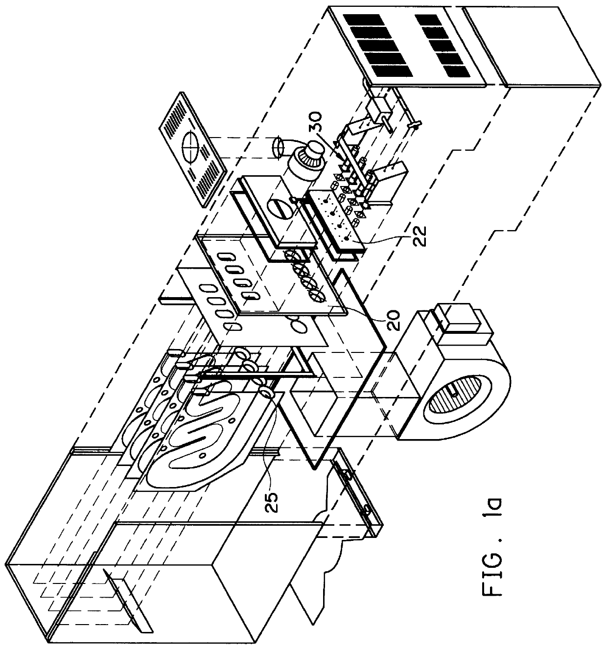
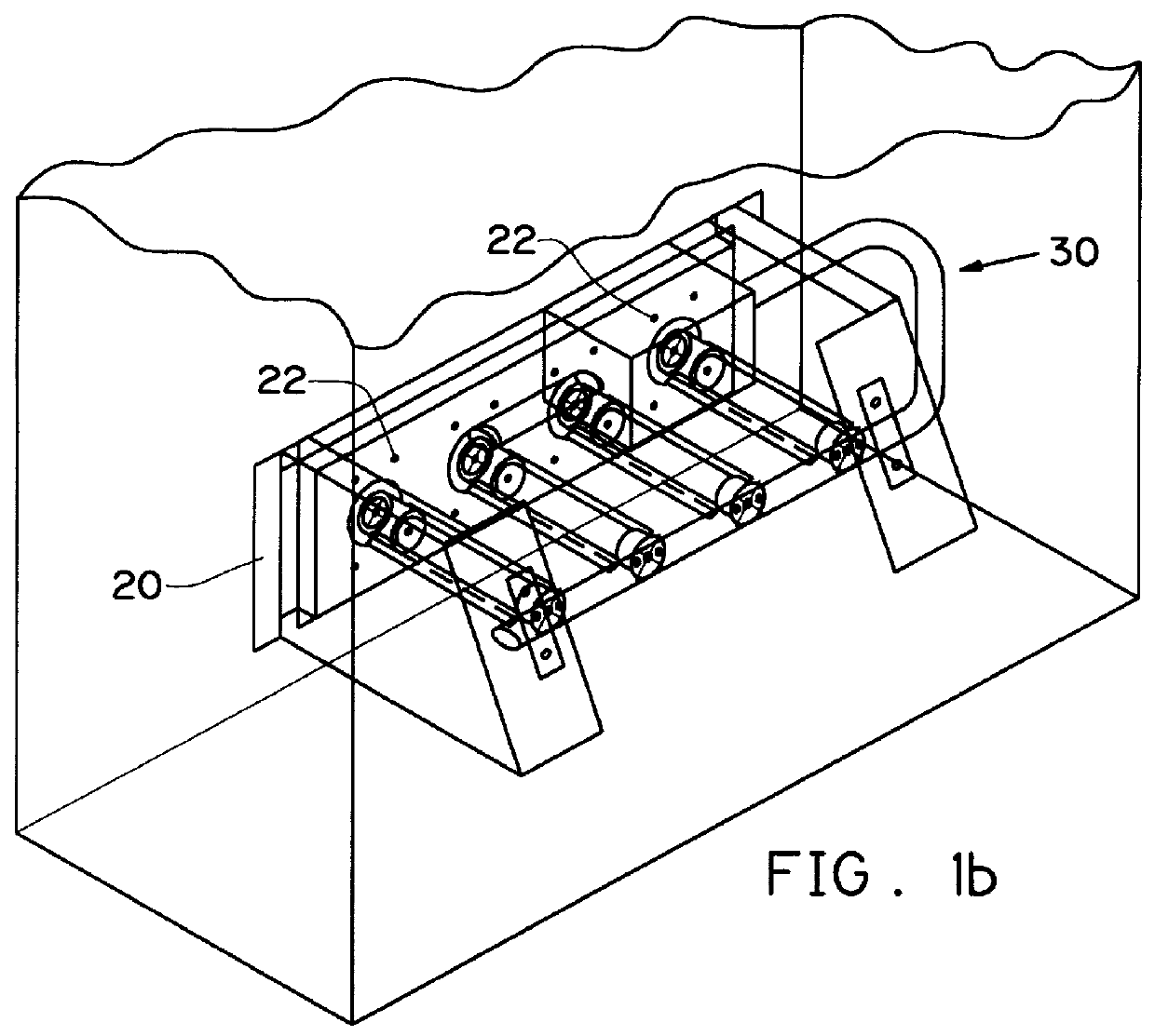
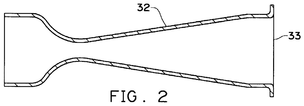
FIG. 1A shows an exploded perspective view of a furnace having four independent combustion chambers 25, each associated with one venturi nozzle 32, for example as shown in FIGS. 2 and 5. FIG. 5 is a cross-sectional diagrammatic view of one combustion chamber 25, as shown in FIG. 1. FIG. 4A is a partial cross-sectional view showing combustion chamber wall 20 or another suitable wall or structural element having swaged secondary air port 23 formed as a hole, according to one preferred embodiment of this invention. It is apparent that the hole can have any suitable shape, such as round, polygonal, crescent or the like, that forms a suitably shaped secondary air jet 45. FIG. 4B is a partial cross-sectional view of combustion chamber wall 20 having swaged secondary air port 23 formed as a slot, according to another preferred embodiment of this invention. It is apparent that the slot can have any suitable shape, such as an arcuate or a crescent shape as shown in FIG. 6B, that forms a suit...


PUM


Abstract

A process and apparatus for combusting fuel which results in reduction of nitrogen oxides and carbon monoxides emissions. Fuel and primary air are preferably premixed and introduced into a combustion chamber. Secondary air is introduced through a plurality of secondary air ports, each preferably shaped as a slot, which are positioned about a venturi nozzle or flame holder disk mounted with respect to a combustion chamber wall. The secondary air flowing through the secondary air ports forms relatively high velocity and momentum secondary air jets that promote rapid mixing of the fuel and primary air mixture into the secondary air flow, such that a combustion flame is established at a partial periphery of the secondary air jets.

Description

1. Field of the InventionThis invention relates to a process and apparatus for reducing the emission of nitrogen oxides and carbon monoxide, particularly in furnaces or heaters fired with natural gas, wherein secondary air is introduced into a combustion chamber by forming a plurality of relatively high velocity secondary air jets that promote rapid mixing of a fuel and primary air mixture into the secondary air flow.2. Description of Prior ArtU.S. Pat. No. 4,511,325 discloses a burner for reducing nitrogen oxides (NO.sub.x) emissions. Make-up air is introduced through delivery ports which are laterally spaced from a fuel injection nozzle and a main air opening. The make-up air is introduced through the air delivery ports at a sufficient pressure so that the air penetrates deep into the combustion chamber.U.S. Pat. No. 4,601,625 teaches a gas burner having axially directed jet members positioned in an opening within a firewall. Fuel and air are premixed and then injected into a comb...

Claims


Application Information

Patent Timeline
Patent Type & Authority Patents(United States)
IPC IPC(8): F23C9/00F23C9/08F23C7/00
CPCF23C9/08F23C7/00
Inventor CARBONE, PHILIP C.BENEDEK, KAREN R.SCHMIDT, STEPHAN E.BENSON, CHARLES E.
Owner GAS TECH INST
Why Eureka
Try Eureka