Method of diagnosing fatigue life of structural steelwork and a member of steelwork having life diagnostic function

a structural steelwork and fatigue life technology, applied in the direction of instruments, magnetic property measurements, material magnetic variables, etc., can solve the problems of bridge fatigue and damage progress, member of steelwork constituting a building is susceptible to fatigue damage, and conventional methods cannot accurately diagnose the actual degree of fatigue damag

Inactive Publication Date: 2000-06-13
NIPPON STEEL CORP
View PDF12 Cites 21 Cited by
  • Summary
  • Abstract
  • Description
  • Claims
  • Application Information

AI Technical Summary

Benefits of technology

It is an object of the present invention to provide a method of easily and accurately diagnosing the degree of fatigue degradation by stress and strain in structural steelwork prior to occurrence of cracking without any limitation on diagnostic locations, and a member of steelwork capable of practicing this method.
By using the method of diagnosing the fatigue life and the member of steelwork having the life diagnostic function according to the present invention, the wall and covering material need not be removed in practicing the fatigue life diagnosis for buildings and bridges. The degree of fatigue degradation by stress and strain in structural steelwork can be easily and accurately diagnosed prior to occurrence of cracking even in a location where an operator cannot access due to the structural limitation.

Problems solved by technology

A member of steelwork constituting a building is susceptible to fatigue damage more or less by vibrations caused by the wind or earthquake after it has been built up.
The fatigue and damage progress in bridges due to repeated vibrations caused by vehicles passing on them.
These conventional methods cannot accurately diagnose an actual degree of fatigue damage to determine whether to repair.
No technique for accurately diagnosing the degree of fatigue damage and determining whether to repair is developed for the above device.
The above conventional techniques, however, detect material degradation caused by changes in microstructures such as phase transformation when a target measurement object is set in a high-temperature state or exposed to radiation.
No description, however, is made for Barkhausen noise measurement conditions under which the degree of fatigue can be accurately detected in an actual structure and the life of the actual structure can be diagnosed, provided that the magnetic head cannot be brought into direct contact with a measurement location due to, e.g., an uneven surface or the presence of a covering material.
Such a diagnosis is performed upon removing a wall or covering material in a building or the like, resulting in high cost.
Neither a method of diagnosing the fatigue life of an actual structure nor a member of steelwork capable of practicing the method is available.
It is, therefore, impossible to bring a sensor or the like into direct contact with the surface of the target measurement object.
The most important problem is a region of the member of steelwork to be measured.
It is very difficult to measure the Barkhausen noise on the uppermost surface because an oxide film or corrugations are present on the uppermost surface of an actual member of structural steelwork.
According to studies of the present inventors, this surface state makes it difficult to bring the magnetic head into tight contact with the member of steelwork.
When the detection depth is smaller than 5 .mu.m, dispersion of the Barkhausen noise due to the surface oxide layer or corrugations increases to degrade the diagnostic accuracy.
When the detection depth is larger than 1 mm, the component of the Barkhausen noise which does not reflect fatigue degradation increases to degrade the diagnostic accuracy.
As previous described, micro-cracking by fatigue is said to tend to occur from the surface of a member.
In particular, fatigue degradation are said to tend to occur from a welding portion or a notch where stress concentrates.
The flow of magnetic excitation fluxes is disturbed near the boundary of these materials, and uniform magnetic excitation cannot be performed accordingly.
This decreases the detection sensitivity of the Barkhausen noise.
It is considerably difficult to apply the magnetic head direct to the welding portion itself and measure the Barkhausen noise.
The edge portion of a member may be predicted to become a micro-cracking source by fatigue because notched corrugations tend to generate on the surface of the edge portion.
It is also difficult to apply the magnetic head direct to the edge portion and measure the Barkhausen noise because the magnetic head cannot be stably applied to the edge portion.
Since this, however, is time-consuming and requires much labor, the measurement area must be minimized.
This disables uniform magnetic excitation, and reduces the detection sensibility of the Barkhausen noise.
In addition, the manner to set the magnetic head becomes difficult.
The diagnostic accuracy cannot be improved even with the area S satisfying 10.sup.-2
However, the members of steelwork in a building or the like cannot be easily applied with the magnetic head because most of the members are covered with the interior finish materials.

Method used


Image

  • Method of diagnosing fatigue life of structural steelwork and a member of steelwork having life diagnostic function
  • Method of diagnosing fatigue life of structural steelwork and a member of steelwork having life diagnostic function
  • Method of diagnosing fatigue life of structural steelwork and a member of steelwork having life diagnostic function

Examples


experimental example 2

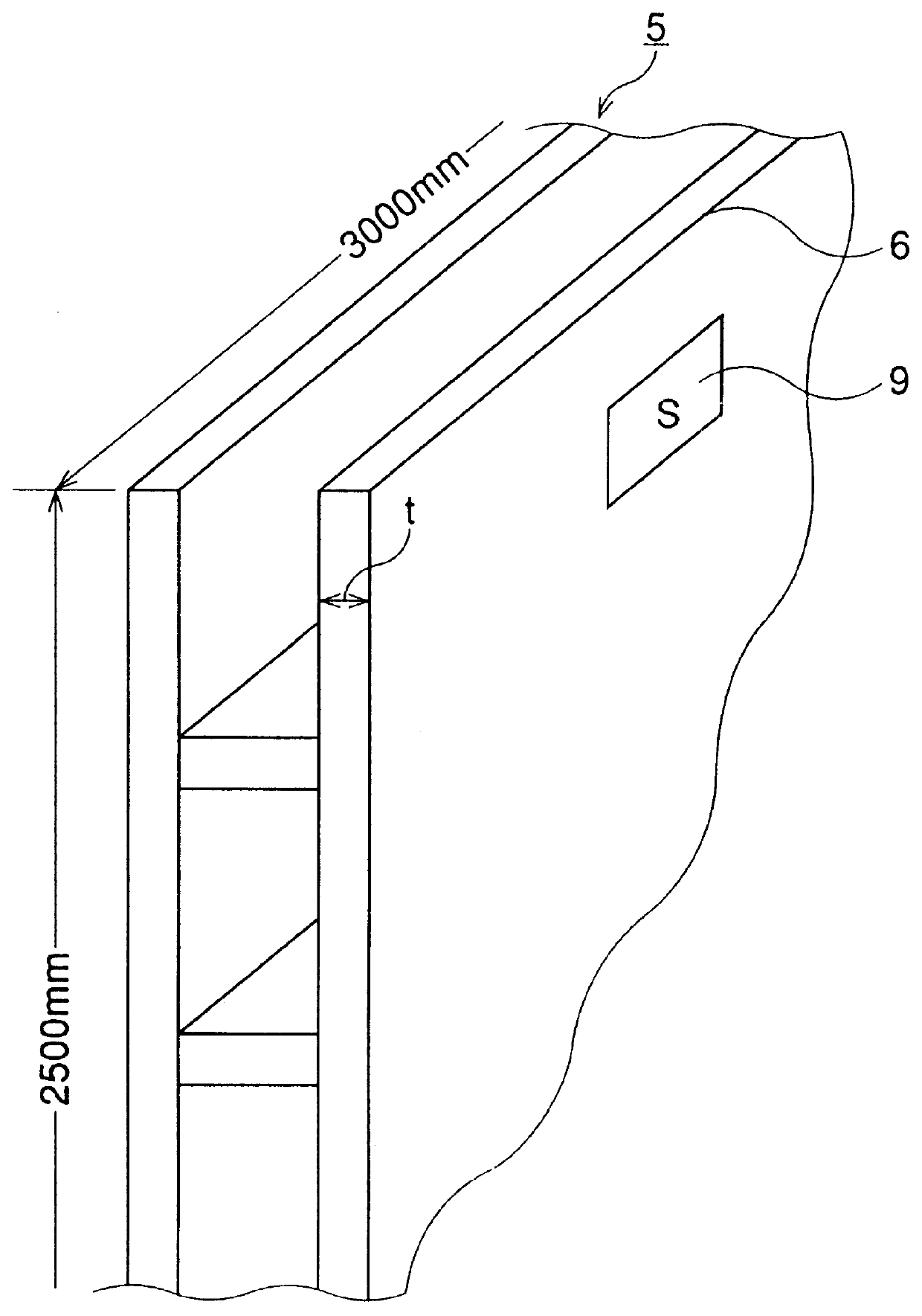
A shear strain of .+-.1% was longitudinally loaded on test members (thickness of member: 5 mm, length: 3,000 mm, width: 2,500 mm) of rolled steel sheet SM400 for welding structure shown in FIG. 2 by using a large test machine to examine on the basis of the load repetition count and the changes in Barkhausen noise whether the fatigue life could be diagnosed. As shown in FIGS. 7 and 8, when an abrupt change in Barkhausen noise can be sensed prior to occurrence of cracking, the determination is made as "diagnosable"; otherwise,"undiagnozable".

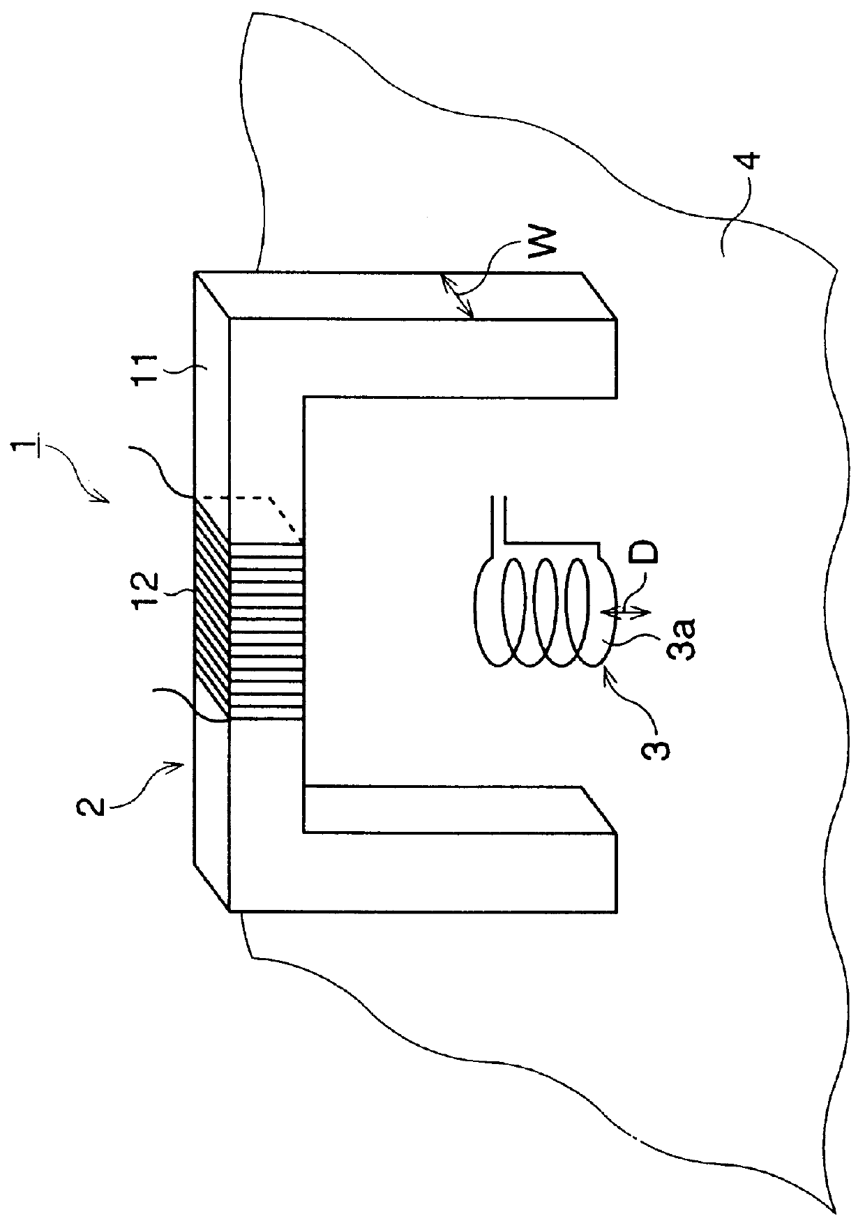
In this experiment, the detection depth of the Barkhausen noise was variously changed to check. A magnetic head 1 having the magnetic excitation head width of 10 mm and the magnetic detection head measurement area of 20 mm.sup.2 was used. The liftoff distance D of the magnetic head 1 was 0.6 mm. The excitation frequency was changed within the range of 2 Hz to 100 Hz and the detection frequency was changed within the range of 10 Hz to 20 MHz to cha...

experimental example 3

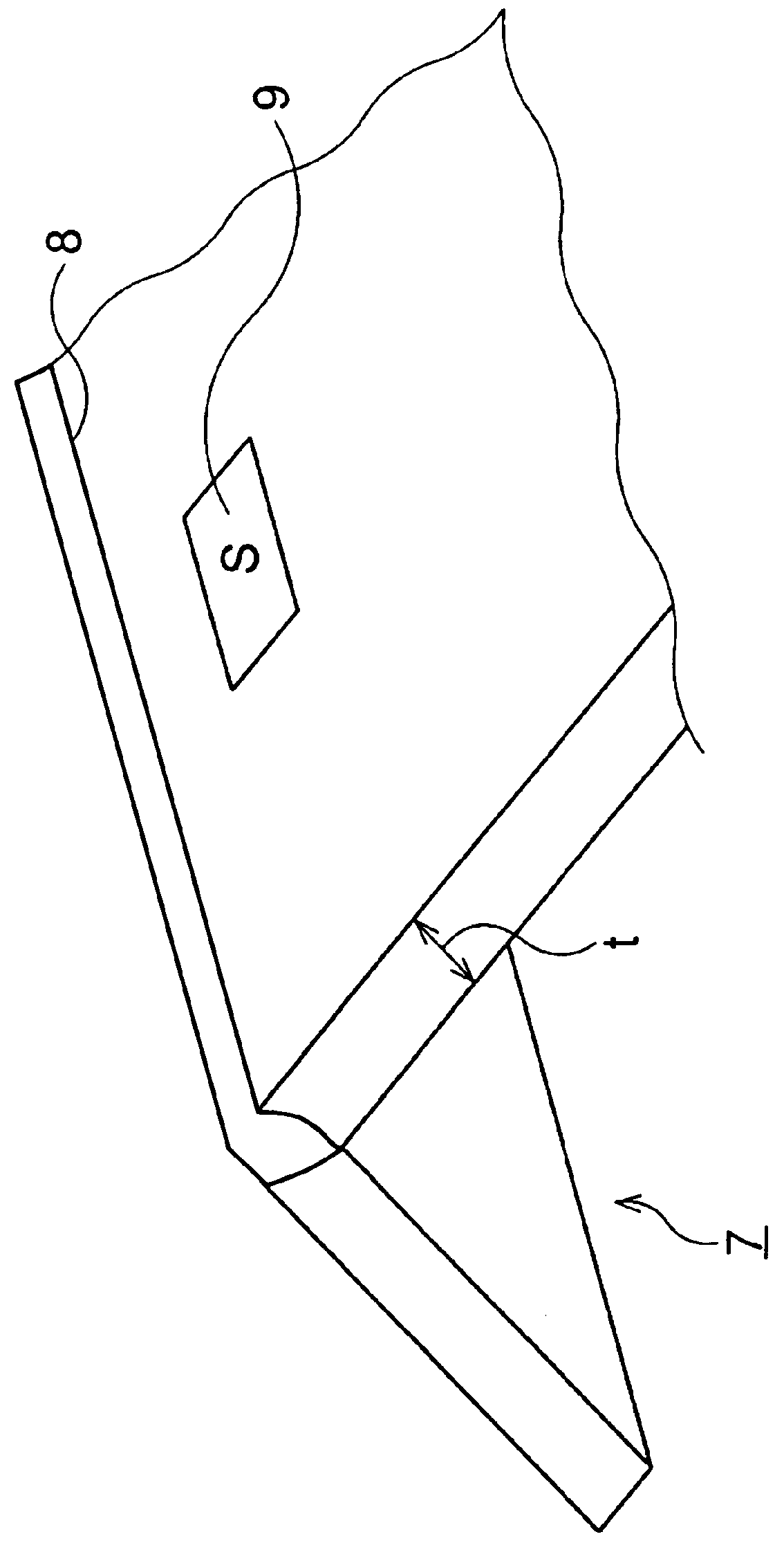
An arbitrary position was selected in a member of structural steelwork shown in FIG. 2, a liftoff distance D of a magnetic head 1 was changed at each position, and the Barkhausen noise was measured 10 times at each liftoff distance D. The magnetic head 1 was identical to that in Experimental Example 2. The excitation and detection frequencies were set to 100 Hz and 10 kHz to 100 kHz, respectively. The detection depth d of the Barkhausen noise was about 200 .mu.m. The maximum, minimum, and average values of the RMS voltages of Barkhausen noise measured 10 times are shown in Table 2.

Judging from the above results, when the liftoff distance D is smaller than 5 .mu.m (0.005 mm), the magnetic head 1 applied to the target measurement surface becomes unstable due to the corrugations of the target measurement surface, and the difference between the maximum and minimum values becomes large. When a diagnosis is performed by one measurement result, the diagnostic accuracy is reduced. When the ...

experimental example 4

Using a member identical to that of Experimental Example 2, a test for loading a repeated strain was conducted, and it was determined on the basis of the load repetition count and the changes in Barkhausen noise whether the fatigue life was diagnosed. A method of determining whether a diagnosis can be performed is identical to that of Experimental Example 2. In this experiment, examinations were made when the position of a measurement portion and its measurement area were variously changed using the edge portion as the reference position. The excitation and detection frequencies were the same as those of Experimental Example 3. The liftoff distance D was set to 0.6 mm. The width w of the magnetic excitation head was 10 mm , and the area which could be measured each time when the magnetic head 1 applied to the target measurement object was 20 mm.sup.2. A total area S.sub.0 of the member used this time was 15.times.10.sup.6 mm.sup.2 (the area on one surface of one steel sheet was 7.5....


PUM

PropertyMeasurementUnit
liftoff distanceaaaaaaaaaa
depthaaaaaaaaaa

Abstract

In a method of diagnosing the fatigue life of structural steelwork according to the present invention, a Barkhausen noise measurement is performed under the condition of 5 mu m< / =d< / =1 mm where d is the detection depth of Barkhausen noise, by using a magnetic head constituted by an air-core coil detection head and a magnetic excitation head obtained by winding a copper wire such as an enameled wire on a U-shaped core made of a soft magnetic material such as a silicon steel sheet or an amorphous magnetic material. The degree of fatigue damage of a target measurement portion is diagnosed using the root-mean-square (RMS) voltage or voltage amplitude value of the Barkhausen noise. According to this method, the degree of fatigue and degradation by stress and strain in the structural steelwork can be accurately diagnosed prior to development of cracking without any limitation on diagnostic locations. A member of steelwork having a life diagnostic function is obtained by mounting the above magnetic head on a brace- or wall-like vibration-damping device made of very low-yield steel. According to this member of steelwork, the wall or covering material of a bridge or the like need not be removed even in practicing a fatigue life diagnosis. The degree of fatigue degradation in structural steelwork can be easily and accurately diagnosed prior to development of cracking even in a location where an operator cannot access due to the structural limitation.

Description

1. Field of the InventionThe present invention relates to a method of diagnosing the fatigue life of structural framework such as buildings, bridges, and other constructions whose main structures are made of steel, and a member of steelwork having a life diagnostic function.2. Description of the Related ArtA member of steelwork constituting a building is susceptible to fatigue damage more or less by vibrations caused by the wind or earthquake after it has been built up. The fatigue and damage progress in bridges due to repeated vibrations caused by vehicles passing on them. To prevent destruction resulted from the fatigue damage, the following conventional methods have been practiced: a method of calculating a degree of strain in a structure in advance and estimating the life of the structure; and a method mainly using visual inspection such as a color check if it is assumed that cracking has occurred due to the fatigue and damage. These conventional methods cannot accurately diagno...

Claims


Application Information

Patent Timeline
Patent Type & Authority Patents(United States)
IPC IPC(8): G01N27/72G01N3/00
CPCG01N27/725G01N2291/02863G01N2203/0073
Inventor SAKAMOTO, HIROAKIINAGUMA, TORUNAKATA, YASUHIROYAZAKI, MITSUHIKO
Owner NIPPON STEEL CORP
Why Eureka
Try Eureka