

Jet pump treatment of heavy oil production sand
- Summary
- Abstract
- Description
- Claims
- Application Information
AI Technical Summary
Benefits of technology
Problems solved by technology
Method used
Image

Examples
Embodiment Construction
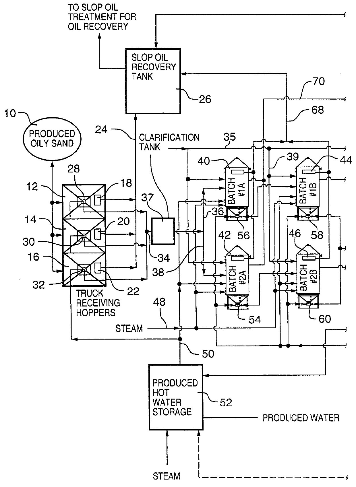
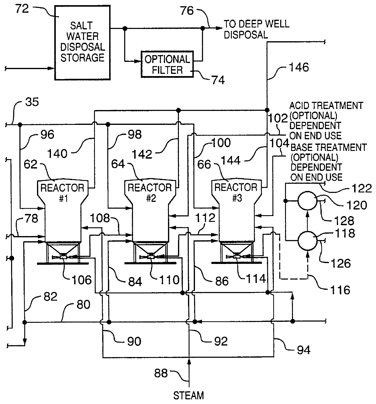
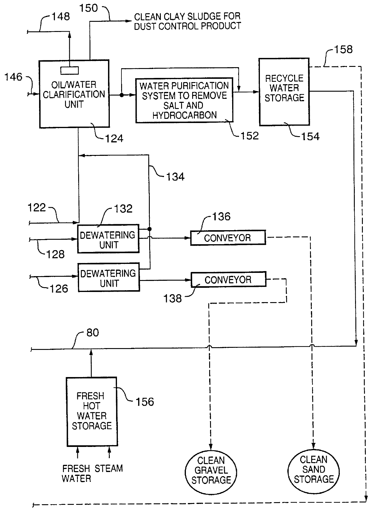
In advance of discussing the details of the invention which resides in the use of a jet pump scrubber under particular operating conditions to surprisingly achieve removal of oily films from sand particles and the like, an overview of one embodiment of the process for treating particulate materials is described with respect to FIGS. 1A, 1B and 1C which constitute sections of the overall block diagram of the process. It is understood that the technology may be applied to removing any type of oily film which is hydrocarbon based from particulate material, such as oils, polymers, paints, creosotes, coal tars, crude oils and the like. In accordance with a preferred embodiment of the invention, the technology is applied to removing oily films from sand particles, such as derived from processing of crude oil mined from heavy oil fields or from tar sands. In particular, the technology may be applied to the treatment of oily coated sand particles derived from a heavy oil processing facility...
PUM
 Abstract
Description
Claims
Application Information