Vehicle heating apparatus having combustor

a technology of heating apparatus and combustor, which is applied in the direction of machines/engines, combustion air/fuel air treatment, transportation and packaging, etc., can solve the problems of increasing the product cost of the vehicle, ineffective use of heat generated by the engine, and insufficient heat generation of the engin

Inactive Publication Date: 2000-06-27
DENSO CORP
View PDF5 Cites 40 Cited by
  • Summary
  • Abstract
  • Description
  • Claims
  • Application Information

AI Technical Summary

Problems solved by technology

In a vehicle having a diesel engine or at a time immediately after starting an engine (e.g., a gasoline engine, a diesel engine), an amount of heat generated from the engine is too small to heat cooling water sufficiently.
However, when a heat exchanger for cooling the exhaust gas of the engine is provided, a space for mounting the heat exchanger in an engine room is necessary, and product cost of the vehicle is increased.
On the other hand, in the co...

Method used


Image

  • Vehicle heating apparatus having combustor
  • Vehicle heating apparatus having combustor
  • Vehicle heating apparatus having combustor

Examples


first embodiment

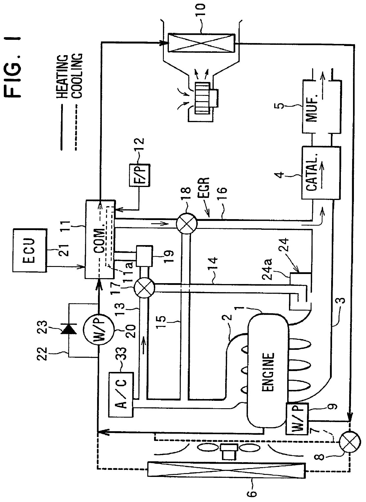
A first preferred embodiment of the present invention will be now described with reference to FIGS. 1-4. In the first embodiment, a heating apparatus of the present invention is applied to a liquid-cooled internal combustion engine (e.g., a water-cooled diesel engine). FIG. 1 shows a circuit of a heating apparatus when a diesel engine 1 stops. Air cleaned in an air cleaner 33 is introduced into the engine 1 through an intake pipe 2.

Exhaust gas discharged from the engine 1 flows through an exhaust pipe 3. In the exhaust pipe 3, there is provided three way catalyst 4 catalyzing oxidation-reduction reaction of hydrocarbon or nitrogen oxide in the exhaust gas and a muffler (silencer) 5 for reducing noise of exhaust gas, flowing from the catalyst 4.

Cooling water for cooling the engine 1 flows through a radiator 6, and is cooled in the radiator 6. Cooling water flowing from the engine 1 returns to the engine 1 through a bypass passage 7 while bypassing the radiator 6. Cooling water flowin...

second embodiment

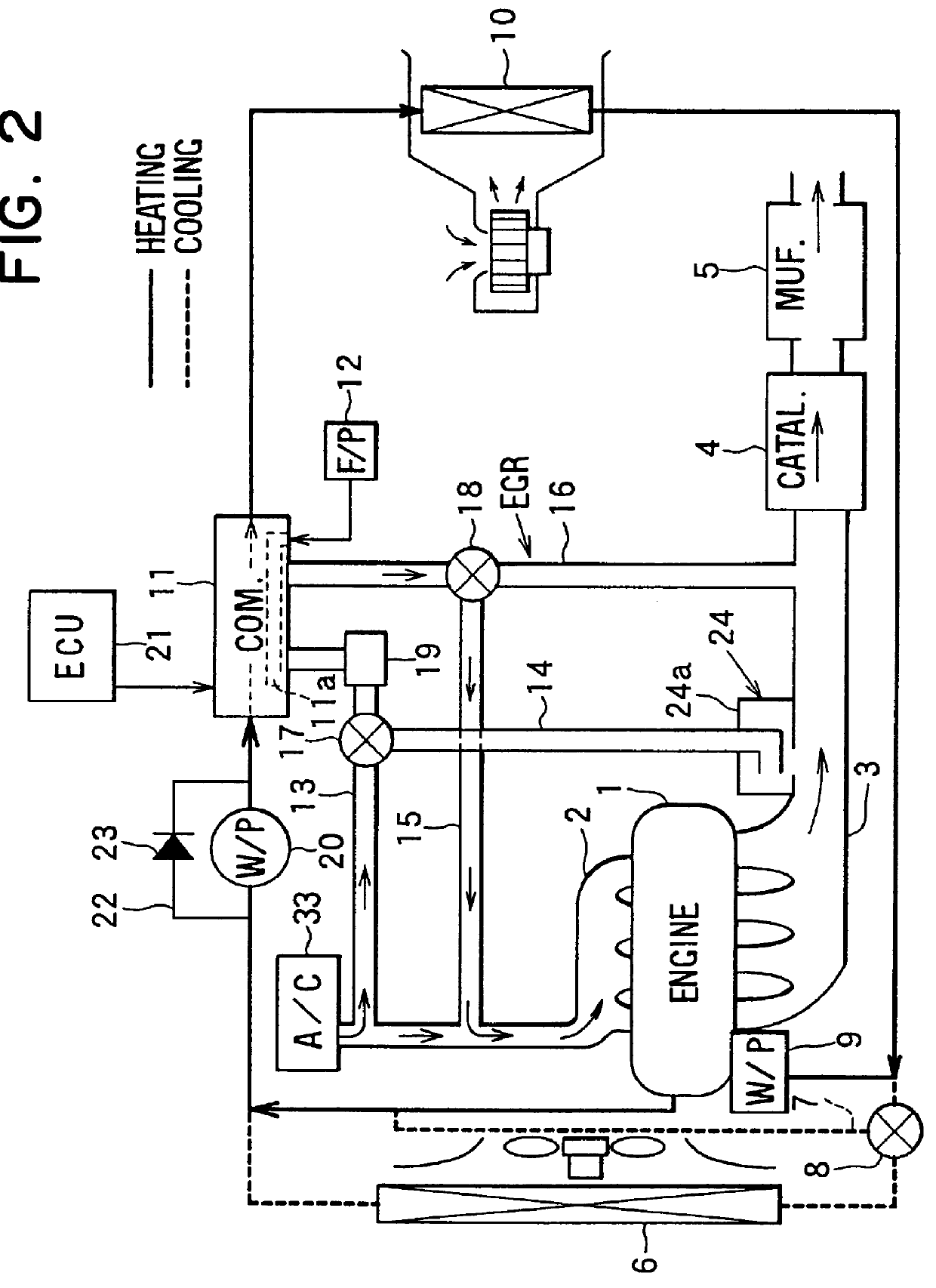
the present invention will be now described with reference to FIGS. 5-7. In the second embodiment, components similar to those in the first embodiment are indicated with the same reference numbers, and the explanation thereof is omitted. FIGS. 5-7 shows a heating apparatus for a vehicle according to the second embodiment.

In the second embodiment, as shown in FIG. 5, there is formed the communication pipe 13 through which the intake pipe 2 of the engine 1 communicates with the intake side of the combustor 11, the communication pipe 14 through which the intake side of the combustor 11 communicates with the exhaust pipe 3. Therefore, intake air of the intake pipe 2 is introduced into the combustor 11 through the communication pipe 13, and exhaust gas of the engine 1 is introduced into the intake side of the combustor 11 through the communication pipe 14. Similarly to the first embodiment of the present invention, the switching valve 17 is provided so that the communication between the ...

third embodiment

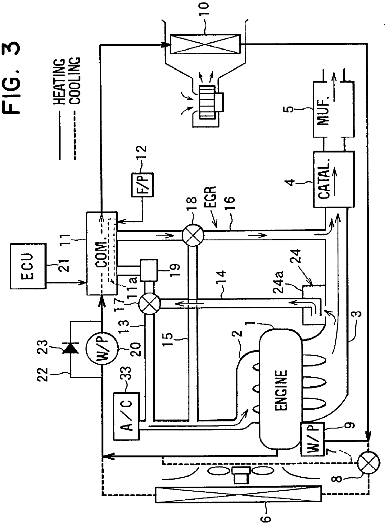
In the third embodiment, as shown in FIG. 8, a throttle valve 2b is disposed between a joining portion 2a of the intake pipe 2 and the air cleaner 33. Therefore, air introduced from the intake pope 2 into the combustor 11 through the communication pipe 13 is restricted by the throttle valve 2b.

When the combustor 11 is operated, fuel supplied from the fuel pump 12 is burned in the combustion chamber of the combustor 11. The operation of the combustor 11 or heat-generating amount from the combustor 11, a fuel amount supplied from the fuel pump 12 to the combustor 11, the electrical water pump 20 are controlled by the ECU 21 based on a set value of a timer switch or a remocon (i.e., remote control) unit and signals detected by a water temperature sensor 21a. The timer switch and the remocon unit are manually operated by a passenger in the passenger compartment. The water temperature sensor 21a detects the temperature of cooling water flowing from the engine 1.

Air cleaned in the air cle...


PUM


Abstract

A heating apparatus for a vehicle includes a heat exchanger for heating air blown into a passenger compartment by using cooling water for cooling an engine as a heating source, and a combustor for heating cooling water flowing into the heat exchanger. When the combustor is stopped, exhaust gas of the engine is introduced into the combustor so that the exhaust gas of the engine is heat-exchanged with cooling water in the combustor, and is introduced into an intake pipe of the engine. Therefore, exhaust gas of the engine, introducing into the intake pipe of the engine, is cooled in the combustor without an additional heat exchanger provided in an engine compartment.

Description

This application is related to and claims priority from Japanese Patent Applications No. Hei. 10-161024 filed on Jun. 9, 1998, No. Hei. 10-263562 filed on Sep. 17, 1998, No. Hei. 10-263563 filed on Sep. 17, 1998, No. Hei. 10-268511 filed on Sep. 22, 1998, No. Hei. 10-268512 filed on Sep. 22, 1998, No. Hei. 10-268514 filed on Sep. 22, 1998, No. Hei. 10-268515 filed on Sep. 22, 1998, No. Hei. 10-268516 filed on Sep. 22, 1998, and No. Hei. 10-329798 filed on Nov. 19, 1998, the contents of which are hereby incorporated by reference.1. Field of the InventionThe present invention relates to a vehicle heating apparatus having a combustor for heating a passenger compartment of the vehicle by burning a fuel, and an exhaust gas recirculation system for recycling exhaust gas.2. Description of Related ArtIn a vehicle having a diesel engine or at a time immediately after starting an engine (e.g., a gasoline engine, a diesel engine), an amount of heat generated from the engine is too small to hea...

Claims


Application Information

Patent Timeline
IPC IPC(8): B60H1/03B60H1/02F01P3/20F02M31/16F02M31/02
CPCB60H1/032B60H1/2206F01P3/20F02M31/163Y02T10/126F01P2060/18F01P2060/10Y02T10/12
Inventor MORIKAWA, TOSHIOSUGI, HIKARUTAKAGI, MASASHIITO, HAJIME
Owner DENSO CORP
Why Eureka
Try Eureka