Large dump truck suspension

a dump truck and suspension technology, applied in the direction of resilient suspensions, vehicle springs, transportation items, etc., can solve the problems of large bending load on the rear axle and rear wheel support system, narrow main frame of the truck, and inability to maintain parts, etc., to achieve the effect of avoiding torsional loading

Inactive Publication Date: 2000-07-11
BHP AUSTRALIA COAL PTY LTD
View PDF11 Cites 47 Cited by
  • Summary
  • Abstract
  • Description
  • Claims
  • Application Information

AI Technical Summary

Benefits of technology

In an alternate form of the invention, the pivotal connection of the suspension means to the frame member, or the frame member itself, allows limited rotation of the hub in a transverse-vertical plane relative to the frame member. The suspension support of the suspension means may be provided with a yoke for supporting a spherical bearing, said spherical bearing engaging bearing surfaces formed in the respective frame member. The yoke may be provided with a transversely extending bush into which is journalled an inner sleeve for pivotal mounting of the body support.
Alternatively, the pivotal mounting of the body support may provide the support for the spherical bearing, said bearing engaging bearing surfaces formed in the respective frame member and eliminating torsional loading on the frame member between the spherical bearing housing on the frame member and the forward attachment means for the hub on the frame member.
The pivotal mounting of the suspension means and the body allows the main frame, the body support and the suspension means to each pivot independently relative to the other two. This enables said loads generated in the tire road interface to be transferred directly into the dump body supports substantially by-passing the frame.
In addition to substantially direct transfer of the dump body loads onto the suspension means, the need for a device such as an anti-sway bar, Panhard rod or similar device for transferring cornering loads between the rear axle and the dump body is eliminated.

Problems solved by technology

This means that much of the cost of operating such trucks is related to moving the empty vehicle weight rather than the payload.
With present designs of truck this leads to a very narrow main frame for the truck and very high bending loads on the rear axle and rear wheel support systems.
The narrow main frame causes shortage of space for maintenance of some components, high stress changes during cornering maneuvers, the need for vertically stiff rear suspension springs and design restrictions on the body.
The net effect is high weight and cost for the main frame, the rear axle, the rear wheel support assemblies and the body.
The travel of the rear suspension system of a fully loaded truck is very limited compared to the scale of the truck.
This limited travel is a result of the need to achieve adequate roll stiffness from the two narrowly spaced rear spring units.
The main frame of these trucks are complex welded steel structures that are heavy (e.g. 16.5 tons for the main frame of a truck with a payload rating of 172 tons), expensive to design, develop and manufacture, and prone to fatigue cracking.
This system of supporting the stiff body causes high variations of stress levels in the main frame of the truck and the body as the truck traverses over uneven ground and during cornering.
This feature causes fatigue problems, high design and fabrication costs and the need for considerable expenditure to limit the unevenness of the ground on which the trucks travel.
This causes very large bending loads to be applied to the main frame of the truck and requires that the main frame by very massive at the mid sections.
It can also cause large stress changes in the body.
During short radius turning maneuvers (frequent occurrences in typical mining operations), this causes severe scrubbing type wear of the tires due to the differential travel distance effect.
The combination of four wide tires on a solid beam type rear axle causes large variations in individual tire loads as the truck traverses uneven ground conditions.
Furthermore these bending loads fluctuate greatly as the truck travels over uneven ground, during cornering and when the dump body is raised during unloading.
While many truck frame design improvements have been suggested over the years, no one design has successfully addressed more than a few of the difficulties which have been outlined above.
The independent frame members arrangement which is described as addressing many of the problems created by uneven terrain is extremely complex and consequently expensive and heavy.
Centrally supported rear wheel pairs provide the potential to overcome some of the problems inherent in currently available large mining trucks, but to date no successful method of exploiting this potential has been established.
In addition to the above, most truck body designs have remained essentially unchanged for many years, being characterized by extremely heavy structures reinforced by means of relatively closely spaced transverse beams assisted by limited longitudinal beams, thereby resulting in a body structure of extremely high weight.
Although in this arrangement, the wear on the sides of the body is reduced, the flat body floor is not compatible with most truck main frame designs and it increases the height of the center of gravity of the truck unless the overall width and / or length of the truck is increased.

Method used


Image

  • Large dump truck suspension
  • Large dump truck suspension
  • Large dump truck suspension

Examples


first embodiment

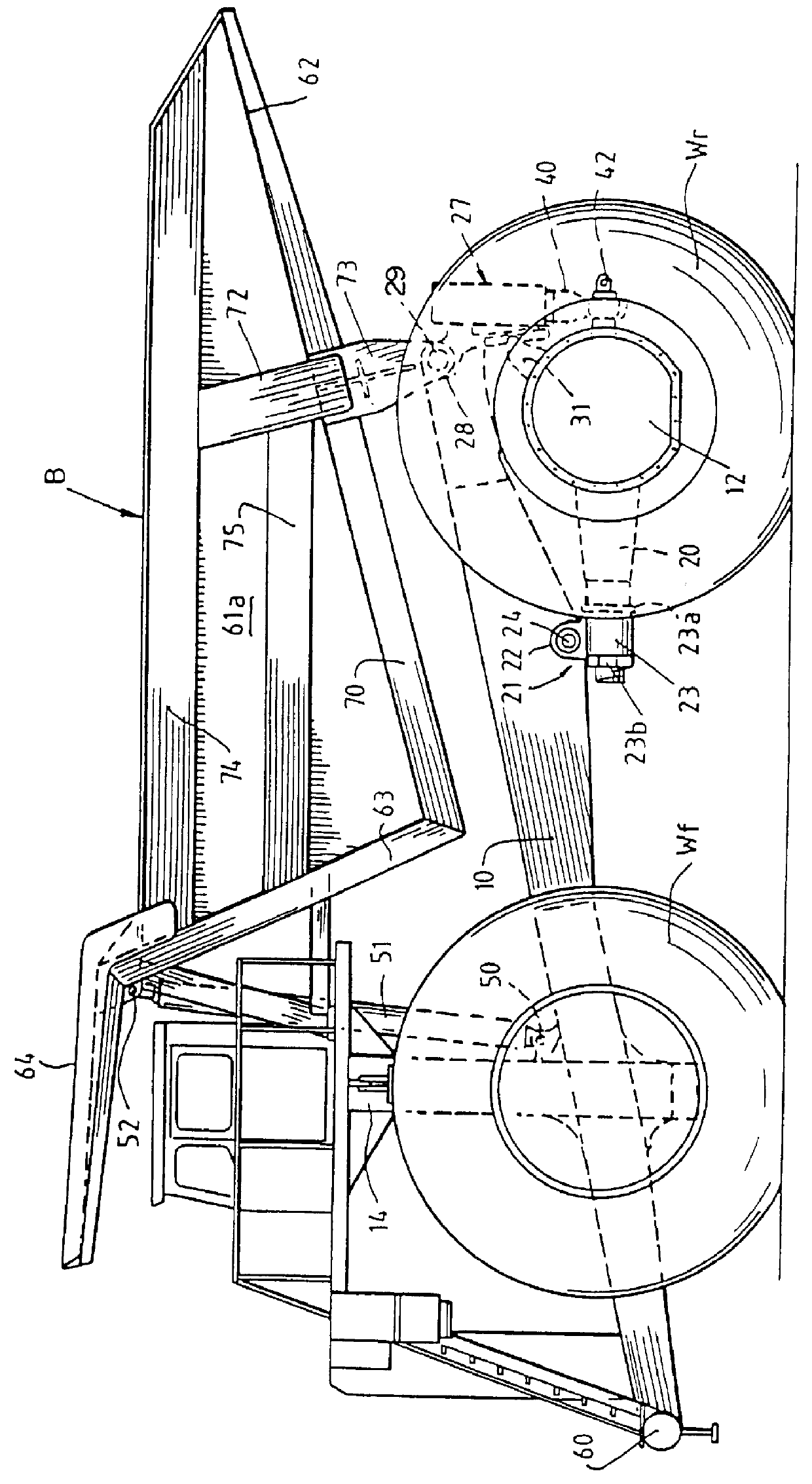
In the present invention shown in FIGS. 8, 9 and 10, the rear wheel mounting hubs 112 and 113 are shown mounted to the longitudinal frame members 110,111 by means of forwardly extending attachment members or mounting arms 120. The attachment members 120 are attached to pivotal mountings 121 which in turn are pivotally secured to respective frame members 110 and 111. The attachment members 120 and the rear wheel mounting hubs 112,113 may be formed separately or as an integral unit.

Each pivotal mounting 121 includes a transverse journal 123 which engages spindle sections or, the ends of a shaft 124 which is attached to frame members 110,111. Rear cross member 160 is formed by connecting the inside ends of shaft 124. Connection 125 at each end of rear cross member 160 can be either a rigid joint, a pin joint or a suitable flexible joint.

Cross member 160 is optional but is useful in that it helps to maintain constant separation between the end portions of attachment members 120 which wo...

second embodiment

In FIGS. 11 and 12, an alternative second embodiment of the suspension / body pivot mounting 233 is illustrated. This embodiment of suspension / body pivot mounting may be substituted for the mounting 133 shown in FIG. 9.

In the alternate embodiment, the arms 235,236 of the suspension mounting member 126 are positioned on either side of the frame member 210, and a cylindrical shaft 237 extends through apertures in both arms and the frame member 210. The cylindrical shaft is received within apertures formed in the body pivot arms 238,239 and secured in position by retainers 240 and retaining bolts 241.

To reduce frictional forces between the cylindrical shaft, arms 235,236, frame member 210 and body pivot arms 238,239, bushings 234 and 244 may be provided.

The bushings 234 fit within the aperture of the frame member 210, and between the arms 235 and 236 of the suspension mounting member 126. Each bushing 234 may be shaped to provide journal bearing sections 231 and spacer bearing sections 2...


PUM


Abstract

PCT No. PCT/AU96/00180 Sec. 371 Date Jul. 11, 1997 Sec. 102(e) Date Jul. 11, 1997 PCT Filed Mar. 29, 1996 PCT Pub. No. WO96/30223 PCT Pub. Date Oct. 3, 1996A suspension system for a large dump truck. The dump truck having a main frame with laterally spaced frame members each associated with a rear wheel mounting hub with a wheel on each of its sides. Each hub is attached to a respective frame member by an attachment member pivotally attached to the respective frame member by a pivotal mounting and a suspension spring pivotally attached to the hub by a spherical bearing and to the respective frame member at a pivot mounting. The connections of the hub allow for limited pivotal movement of the hub about transverse and longitudinal axes relative to the frame members. A dump body is pivotally attached to the frame members at the pivot mounting or to the rear and above a suspension pivotal connection at a body pivotal connection.

Description

This invention relates to suspension systems and configurations for the main structural components of very large trucks of the type used in mining operations.There is much commonality between currently available large mining trucks made by different manufacturers and the following observations are generally applicable regardless of the truck manufacturer:The empty vehicle weight is a high proportion of the maximum gross vehicle weight. Typically the ratio of payload to empty vehicle weight is only about 1.4:1. This means that much of the cost of operating such trucks is related to moving the empty vehicle weight rather than the payload.The total width of the four rear tires is large compared to the total width of the truck. Typically 65% of the total width of a truck is taken up by the four rear tires. With present designs of truck this leads to a very narrow main frame for the truck and very high bending loads on the rear axle and rear wheel support systems. The narrow main frame c...

Claims


Application Information

Patent Timeline
Patent Type & Authority Patents(United States)
IPC IPC(8): B60G13/00B60G21/055B60G3/00B60G9/02B60G7/02B60G21/00B60G3/14B60G9/00B60G9/04B60G7/04B60P1/04B60P1/28
CPCB60G3/14B60G7/02B60G9/02B60G13/001B60G21/0551B60G2200/10B60G2200/132B60G2200/32B60G2200/322B60G2202/135B60G2204/128B60G2204/129B60G2204/143B60G2204/416B60G2204/4232B60G2204/45B60G2300/02B60G2300/026B60G2300/36B60G2800/20B60G2200/46F16C11/045
Inventor PREM, HANSBARTLEY, FRANCIS ALLENMILLER, DARIN ROSSDICKERSON, ALAN WILLIAM
Owner BHP AUSTRALIA COAL PTY LTD
Why Eureka
Try Eureka