Power output apparatus, method of controlling power output apparatus, and driving system with power output apparatus incorporated therein

a technology of power output apparatus and power output device, which is applied in the direction of driver interaction, gas pressure propulsion mounting, electric devices, etc., can solve the problems of engine to be driven at extreme low energy efficiency of the whole apparatus, and engine to be driven at driving points of low energy efficiency or poor emission, etc., to achieve the effect of enhancing the energy efficiency of the whole power output apparatus

Inactive Publication Date: 2000-07-11
TOYOTA JIDOSHA KK
View PDF25 Cites 97 Cited by
  • Summary
  • Abstract
  • Description
  • Claims
  • Application Information

AI Technical Summary

Benefits of technology

One object of the present invention is thus to provide a power output apparatus and a method of controlling the same that enhance the energy efficiency of the whole power output apparatus.
In the second method of the present invention, it is also desirable that the step (d) further includes the steps of: (h) when a different target power is set, estimating a driving state of the engine based on a revolving speed of the output shaft of the engine and a state of the energy adjustment means; and (i) controlling the energy adjustment means and the drive motor, so as to enable power output from the engine to be subjected to torque conversion and output to the drive shaft, based on the estimated driving state of the engine. With a variation in target power, this structure enables the power output from the engine to be subjected to torque conversion and to be output to the drive shaft with a high efficiency.

Problems solved by technology

In the conventional power output apparatuses, however, problems, such as an extremely low energy efficiency of the whole apparatus or an extremely poor emission, arise in some cases.
Without the active control of the driving point of the engine, this often causes the engine to be driven at driving points of low energy efficiency or poor emission.

Method used


Image

  • Power output apparatus, method of controlling power output apparatus, and driving system with power output apparatus incorporated therein
  • Power output apparatus, method of controlling power output apparatus, and driving system with power output apparatus incorporated therein
  • Power output apparatus, method of controlling power output apparatus, and driving system with power output apparatus incorporated therein

Examples


first embodiment

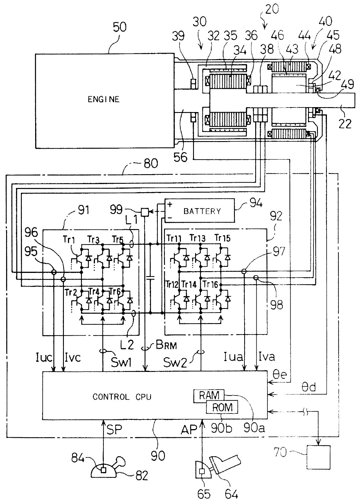
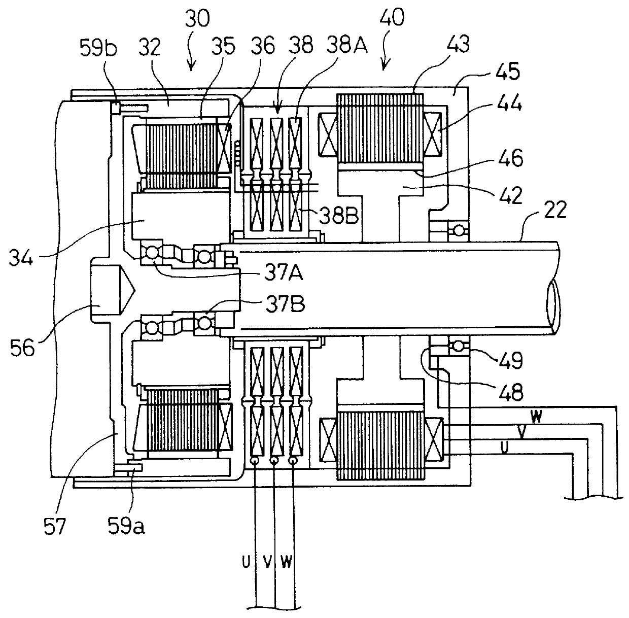
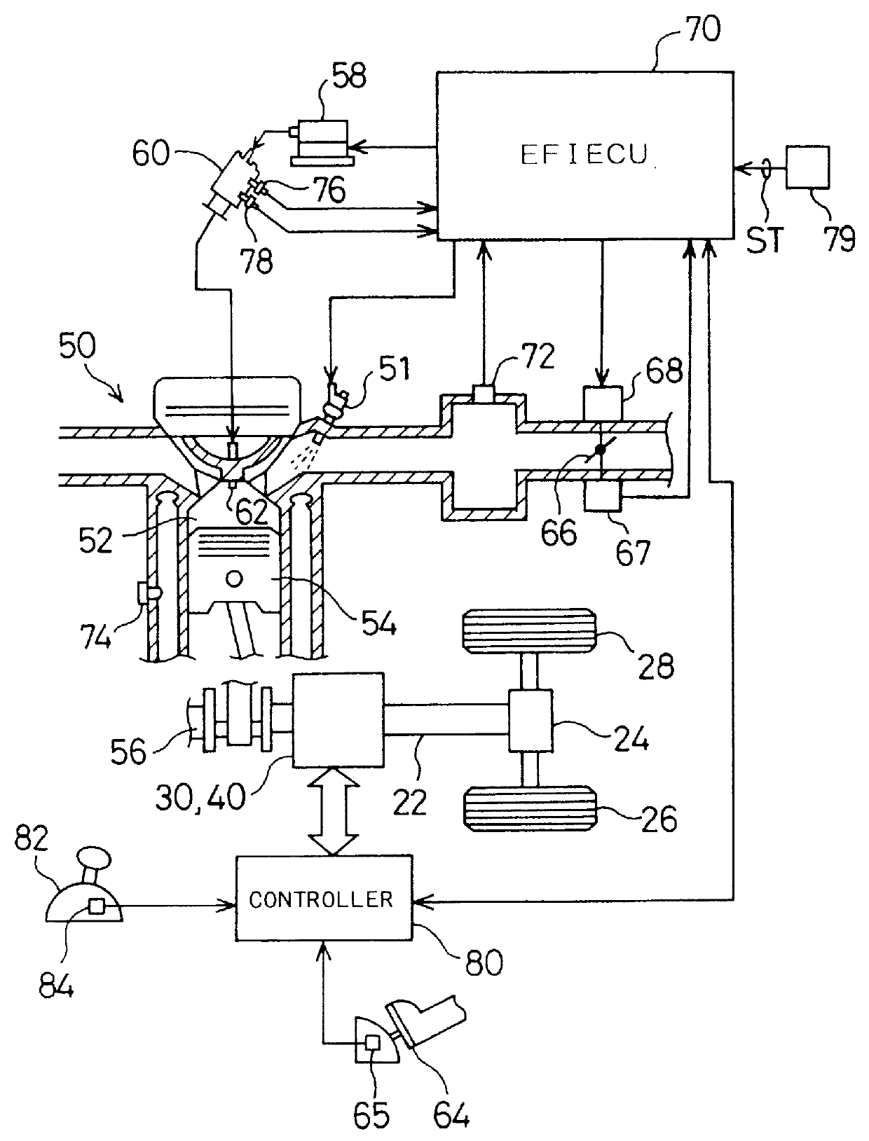
Preferable embodiments of the present invention are described hereafter. FIG. 1 is a schematic view illustrating structure of a power output apparatus 20 as a first embodiment according to the present invention; FIG. 2 is a cross sectional view illustrating detailed structures of a clutch motor 30 and an assist motor 40 included in the power output apparatus 20 of FIG. 1; and FIG. 3 is a schematic view illustrating general structure of a vehicle with the power output apparatus 20 of FIG. 1 incorporated therein. The general structure of the vehicle is described first for the convenience of description.

Referring to FIG. 3, the vehicle is provided with an engine 50 driven by gasoline as a power source. The air ingested from an air supply system via a throttle valve 66 is mixed with fuel, that is, gasoline in this embodiment, injected from a fuel injection valve 51. The air / fuel mixture is supplied into a combustion chamber 52 to be explosively ignited and burned. Linear motion of a pis...

second embodiment

When the driver steps on the accelerator pedal 64 by a relatively large amount, the power output apparatus 20A of the second embodiment controls the engine 50, the clutch motor 30, and the assist motor 40, based on the output energy at a driving point to which the engine 50 can smoothly shift from the current driving point, instead of the output energy Pd corresponding to the step-on amount of the accelerator pedal 64. This structure enables the driving point of the engine 50 to be smoothly shifted to the driving point giving the output energy Pd corresponding to the step-on amount of the accelerator pedal 64, thereby effectively preventing the engine 50 from stalling or stopping due to an abrupt change of the driving point of the engine 50.

Like the first embodiment, the power output apparatus 20A of the second embodiment sets the torque Te and the revolving speed Ne at a specific driving point, which attains the highest possible efficiency among the respective driving points on eac...

third embodiment

FIG. 22 shows the operations in the power output apparatus 20B of the third embodiment when the driver steps on the accelerator pedal 64 to a relatively large depth. By way of example, it is assumed that the driver steps on the accelerator pedal 64 by a relatively large amount at a time point t1 to change the accelerator pedal position AP from a value AP1 to another value AP2. The change of the accelerator pedal position AP causes the target torque Te* and the target revolving speed Ne* of the engine 50 to be newly set based on the new accelerator pedal position AP by the processing of steps S100 through S104 in the torque control routine of FIG. 5. The engine 50 is subsequently controlled at step S111 in the same routine, based on the target engine torque Te* and the target engine speed Ne*. In order to drive the engine 50 at the driving point defined by the target engine torque Te* and the target engine speed Ne*, the throttle valve position control routine of FIG. 12 is carried o...


PUM


Abstract

A power output apparatus 20 includes a clutch motor, an assist motor, and a controller. The clutch motor and the assist motor are controlled by the controller to enable the power output from an engine to a crankshaft 56, and expressed as the product of its revolving speed and torque, to be converted to the power expressed as the product of a revolving speed and a torque of a drive shaft and to be output to the drive shaft. The engine can be driven at an arbitrary driving point defined by a revolving speed and a torque, as long as the energy or power output to the crankshaft is identical. A desired driving point that attains the highest possible efficiency with respect to each amount of output energy is determined in advance. In order to allow the engine to be driven at the desired driving point, the controller controls the clutch motor and the assist motor as well as the fuel injection and the throttle valve position. Such control procedures of the power output apparatus enhance the energy efficiency of the whole power output apparatus.

Description

BACKGROUND OF THE INVENTION1. Field of the InventionThe present invention relates to a power output apparatus, a method of controlling a power output apparatus, and a driving system with a power output apparatus incorporated therein. More concretely, the present invention pertains to a power output apparatus for outputting power generated by an engine to a drive shaft at a high efficiency and a method of controlling such a power output apparatus, as well as a driving system with such a power output apparatus incorporated therein.2. Description of Related ArtIn known power output apparatuses mounted on a vehicle, an output shaft of an engine is electromagnetically linked with a drive shaft, which connects with a rotor of a motor, by means of an electromagnetic coupling, so that power of the engine is transmitted to the drive shaft (as disclosed in, for example, JAPANESE PATENT LAYING-OPEN GAZETTE No. 53-133814). The electromagnetic coupling of the power output apparatus transmits par...

Claims


Application Information

Patent Timeline
Patent Type & Authority Patents(United States)
IPC IPC(8): B60K6/00B60L11/12B60K6/04B60L11/02H02K51/00B60K1/00B60K1/02B60K17/34B60K17/356B60K6/20B60K6/44B60K6/445B60K6/448B60K6/52B60L50/15B60L50/16B60W10/06B60W10/08B60W10/26B60W20/00H02K7/11H02K7/18H02P9/04H02P15/00
CPCB60K6/40B60K6/44B60K6/448B60K6/52B60L11/12B60W10/06B60W10/08B60W10/26B60W20/00H02K51/00B60L11/123B60L11/14B60L11/1861B60L15/007B60L15/2009B60K6/365B60K1/02Y02T10/6217B60K17/356B60K2006/262B60L2220/52B60W2710/0666Y02T10/56Y02T10/623Y02T10/6243Y02T10/6265Y02T10/6286Y02T10/641Y02T10/646Y02T10/7005Y02T10/7077Y10S903/903Y10S903/951Y10S903/91Y10S903/916Y02T10/648B60L2210/40B60L2220/14B60L2240/12B60L2240/421B60L2240/423B60L2240/425B60L2240/441B60L2240/443B60L2240/486B60L2250/24B60L2250/26B60L2260/28B60L2260/44B60L2270/145Y02T10/7044Y02T10/705Y02T10/7241Y02T10/7275B60L50/15B60L50/61B60L50/16Y02T10/40Y02T10/62Y02T10/64Y02T10/70Y02T10/72Y02T10/7072B60K6/22B60W20/10
Inventor MAEDA, TOMOHARUNII, YOSHIHIDESASAKI, SHOICHIKOTANI, TAKESHIYAMADA, EIJIKAWABATA, YASUTOMO
Owner TOYOTA JIDOSHA KK
Why Eureka
Try Eureka