System and method for accurately determining remaining battery life

a technology of accurate determination and battery life, applied in secondary cell servicing/maintenance, instruments, electrochemical generators, etc., can solve the problems of reducing affecting the accuracy of battery life indicators, and affecting the accuracy of conventional battery life indicators

Inactive Publication Date: 2000-07-11
QUALCOMM INC
View PDF4 Cites 105 Cited by
  • Summary
  • Abstract
  • Description
  • Claims
  • Application Information

AI Technical Summary

Problems solved by technology

However, unlike ideal voltage sources, which have zero internal resistance, batteries have non-zero internal resistance, which is often neglected in the design of electrical systems such as remaining battery life indicators.
As a battery's chemistry degrades, its ability to hold a charge also degrades.
Current trends in re-chargeable battery technology are resulting in discharge curves with sharper knees, which may magnify errors associated with conventional battery life indicators.
A high discharge rate, a drop in temperature, or an extended storage period reduces battery capacity and life span and causes the discharge curve to drop-off sooner.
Most batteries have a limited shelf life, which is the time required for the voltage of an unused battery to drop below a predetermined percentage of its original voltage.
Unfortunately, such gauges are often deceptive and do not account for the knee in the voltage discharge curve or changes of the discharge curve with temperature, discharge rate, battery age, and so on.
This approach, however, has significant limitations.
Over time, remaining battery life as indicated by simply measuring the battery volt

Method used


Image

  • System and method for accurately determining remaining battery life
  • System and method for accurately determining remaining battery life
  • System and method for accurately determining remaining battery life

Examples


Embodiment Construction

While the present invention is described herein with reference to illustrative embodiments for particular applications, it should be understood that the invention is not limited thereto. Those having ordinary skill in the art and access to the teachings provided herein will recognize additional modifications, applications, and embodiments within the scope thereof and additional fields in which the present invention would be of significant utility.

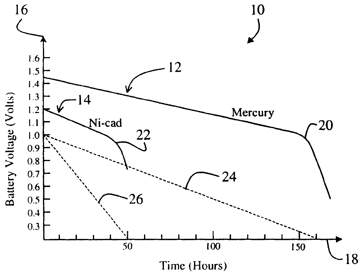
The following review of discharge curves for conventional batteries is intended to facilitate an understanding of the present invention.

FIG. 1 is a graph 10 showing a discharge curve 12 for a conventional D-size mercury battery with an initial current draw of 100 mA and a discharge curve 14 for a conventional nickel-cadmium (Ni-cad) battery with an initial current draw of 100 mA. The graph 10 includes a vertical battery voltage axis 16 labeled in volts and a time axis 18 labeled in hours. The mercury discharge curve 12 descends relatively s...


PUM


Abstract

A system for providing an accurate indication of the remaining life of a battery. The system includes a first circuit that provides a control signal. A second circuit employs an internal resistance value of the battery and a battery voltage to provide the indication of remaining battery life in response to the control signal. In a specific embodiment, the second circuit includes a third circuit that measures the internal resistance of the battery in response to the control signal. The third circuit also includes a circuit for measuring an output current and an output voltage of the battery at varying battery loads. The circuit for measuring an output current includes an ammeter and a switching load. In a more specific embodiment, the switching load is implemented as a transmitter that is selectively activated via the control signal. A fourth circuit, included in the second circuit, provides the indication of remaining battery life in response to the internal resistance. The fourth circuit also includes a circuit for selecting a battery discharge curve in accordance with the internal resistance. Software running on the first circuit generates the estimate based on the discharge curve, which is subsequently displayed via a display.

Description

I. Field of InventionThis invention relates to batteries. Specifically, the present invention relates to systems and methods for indicating a charged state of a rechargeable battery and for indicating when the battery should be replaced.II. Description of the Related ArtBatteries are designed to provide approximately constant voltages to a variety of applications ranging from electronic amplifiers and receivers in wireless phones to automobiles. Such applications often require accurate battery gauges or indicators to indicate remaining battery life. Accurate battery life indicators are particularly important in applications such as wireless phones, where rechargeable batteries are common, and knowledge of remaining battery life is desirable.A battery often includes two metal electrodes immersed in an electrolyte having a depolarizing mix. Batteries are often named in accordance with the type of electrolyte employed such as nickel-cadmium, alkaline-manganese, lead storage, mercury, z...

Claims


Application Information

Patent Timeline
IPC IPC(8): G01R31/36H01M10/42H01M10/44G01R31/392G01R31/389H01M10/48H02J7/00
CPCG01R31/3651G01R31/3662G01R31/3693H01M10/44H02J2007/005G01R31/3647G01R31/367G01R31/389H02J7/0048H02J7/005Y02E60/10H02J7/00
Inventor PRITCHARD, JEFFREY A.
Owner QUALCOMM INC
Why Eureka
Try Eureka