While there are
system organization wherein the control subsystem and the switch subsystem are provided on separate nodes (the node in which the control subsystem is provided is referred to as the "central office" and the node in which the switch subsystem is provided is referred to as the "remote office"), these have the control subsystem and the switch subsystem permanently connected by a
dedicated line, thus making it impossible to make connections other than those which are set.
Hence, such
system organization are not sufficiently flexible to be applied to situations in which dynamic connections of the remote offices is required, situations of
dynamic switching to other central offices in failure of the central office, and situations wherein the central office is merged into the remote office side to solely control the enlarged switch subsystem by a control subsystem.
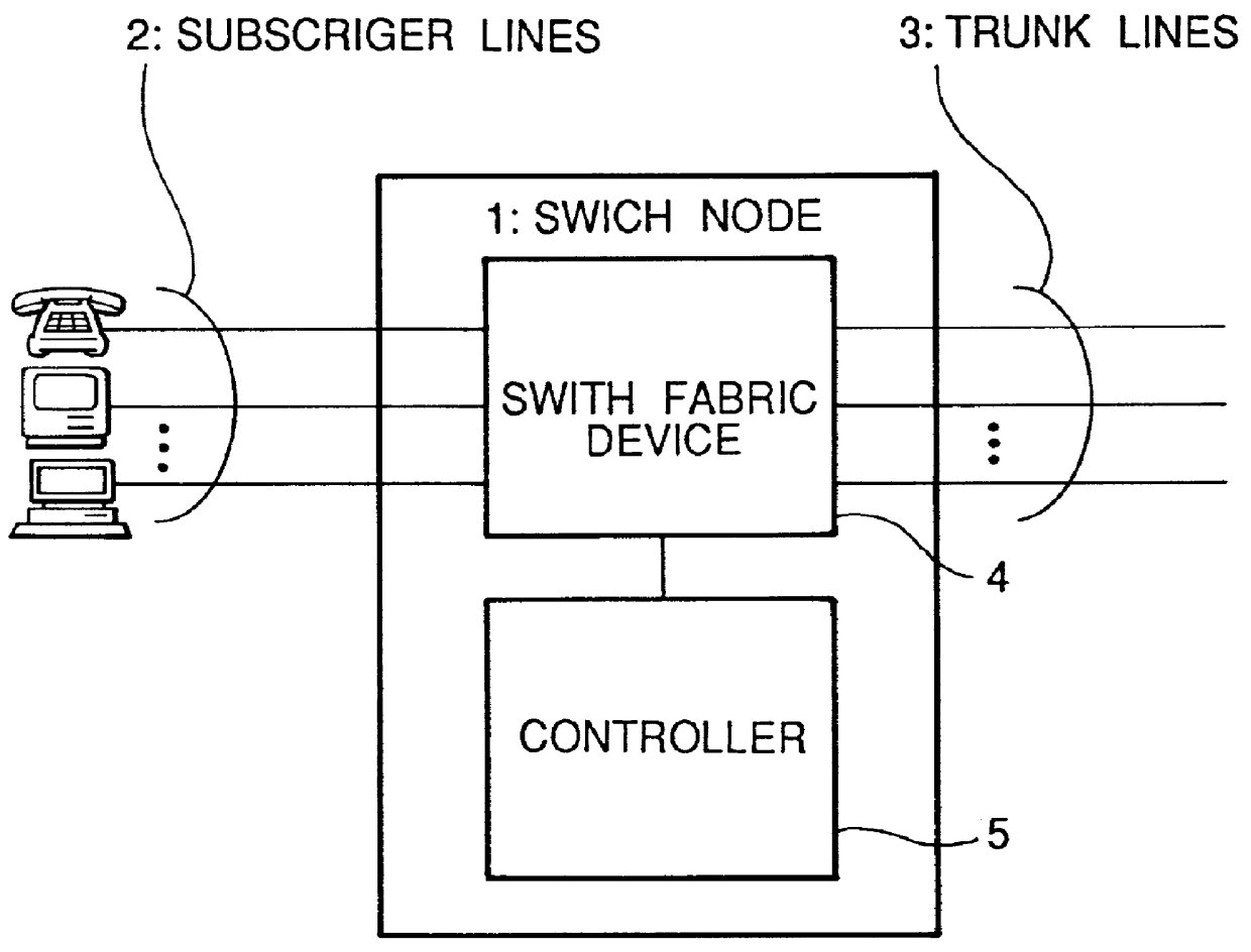
While the controller 5 uses a high-performance processor in order to simultaneously control multiple subscriber lines 2 and
trunk lines 3, since such high-performance processors have extremely high
processing capacity, the
processing capacity often exceeds that required by the switch fabric device 4, thus resulting in surplus
processing capacity.
(1) In the structure shown in FIG. 4, the central office 10 and the remote offices 20 are connected one-to-one by the dedicated lines 16, thus requiring general subchannels 14, dedicated lines 16 and remote office
transmitter-receivers 21 to be provided in numbers proportional to the number of remote offices being controlled, and also requiring the channel
multiplexer 13 and the remote controller 15 to be expanded to accommodate the number of remote offices. For this reason, if the number of remote offices becomes too numerous, the overall network requires an extremely large number of devices, hence greatly increasing the cost.
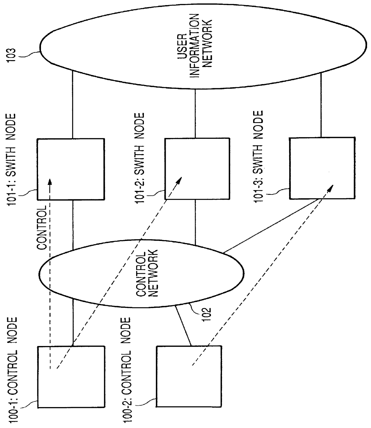
(2) Additionally, since the control subsystem and the switch subsystem are permanently connected by means of dedicated lines, it is not possible to make any connections other than those which are set up. For example, the system is not flexible enough to perform dynamic connections of the remote offices with low usage to share control information links and reduce the
network cost, or to dynamically switch to other central offices when the central office is down.
(3) Additionally, the communication means or methods for the case of
direct control in which the controller and the switch fabric devices are in the same node and the case of
remote control in which the controller and the switch fabric devices are located remotely are different, so that the application program must include separate codes for
direct control and
remote control. This courses high development cost and low flexibility.
(4) Furthermore, since the
control data is transferred through channel commands in the case of
remote control, the
software overhead for the preparation, activation and interrupt processing for channel commands is large and inefficient.
(5) Also, since the transmission of data between the remote controller 15 of the central office and the remote office data sender-receivers 21 of the remote offices is performed by the remote read access command, such as the RCM command in the case of remote control, the time
delay due to spatial propagation increases as the distance between the central office and the remote offices increases, thus extending the
waiting time until the remote controller 15 receives confirmation signals from the remote office data sender-receivers 21 so as not to allow shifting to the next
data transmission. In this way, the decrease in performance is considerable in the case of remote control over long distances.
(6) Furthermore, as a conventional method for identifying and controlling a plurality of switch fabric devices, the designation of channel numbers 40 and 60 as shown in FIG. 5 and the switching of
control data by switching the value of the base register (b) as shown in FIG. 6 are combined. However, when designating channel numbers, the number of remote offices capable of being controlled is limited by the length of the channel number field, and in the base register switching method the data configurations of the switch fabric devices must be made completely identical, thus making this system unsuitable for general applications and poor in flexibility.
(7) Additionally, in switching systems connected by LANs, the switching system is distributed over a range covered by a LAN by dividing the system into a plurality of modules such as a switching module and a central processing module. Even if these distributed systems are introduced in the network, the
network structure is still the same as the one, constructed form conventional switch system. Each switching systems are self-contained and independent of each other, thus giving the network overall an inflexible structure which is unsuitable for general applications and poor in flexibility.
(8) Furthermore, in switching systems connected by LANs, the network is constructed under the assumption of confinement to a local area, so that there are a variety of restrictions such as restrictions to the number of modules able to communicate and the distance between modules.

