
Heat resisting alloy for exhaust valve and method for producing the exhaust valve

Inactive Publication Date: 2000-08-08
DAIDO STEEL CO LTD
View PDF6 Cites 15 Cited by
  • Summary
  • Abstract
  • Description
  • Claims
  • Application Information

AI Technical Summary

Benefits of technology

This invention is made in order to solve the aforementiond problems in the prior art, it is an object to provide a heat resisting alloy which is inexpensive in consequence of the Ni content on a relatively low level, excellent in the cold workability and possible to be formed into the exhaust valve at a low price through the cold working, and it is another object to provide a method for producing the exhaust valve having excellent properties equivalent to that of the conventional exhaust valve by using the aforementioned heat resisting alloy without increasing the production cost.

Problems solved by technology

Although the aforementioned Ni-based super alloy is an alloy excellent in high-temperature strength, high-temperature oxidation resistance and high-temperature corrosion resistance, there is a problem in the cost since the alloy contains expensive Ni as much as a little more than 70 wt %.
However, further decrease of Ni content causes problems in properties of the alloy and it is difficult realistically to further reduce the Ni content in the alloy.
Namely, if the Ni content is further decreased, stability of the structure at a high-temperature is detriorated owing to increase of Fe, .eta.-phase (Ni.sub.3 Ti) which is a brittle phase is precipitated during the long time application at a high-temperature, thereby bringing deterioration in the high-temperature strength and the toughness at a room temperature of the alloy.
Thus, there is a limit naturally in the decrease of the Ni content for a reason of the problem in the properties of the alloy.
However, there is a problem in the aforementioned conventional method in that it is necessary to form the head portion through two steps consisting of the preforming by the electric upsetting after the preforming.
The head portion formed through the hot upsetting is not so excellent in the dimensional accuracy and it is required to completely remove defects on a surface of the formed head portion, therefore there are the other problems in that cutting amount in the finishing process is apt to increase and times required for the finishing is also apt to become longer.
All of these problems are causes for increase of the production cost and are required to be solved.
However, the heat resisting alloys proposed and used practically up to the present have been developed assuming the hot working in all cases, therefore it has been difficult to form the head portion by carring out the cold or warm forging to the raw material of these alloys.

Method used


Image

  • Heat resisting alloy for exhaust valve and method for producing the exhaust valve

Examples


example 1

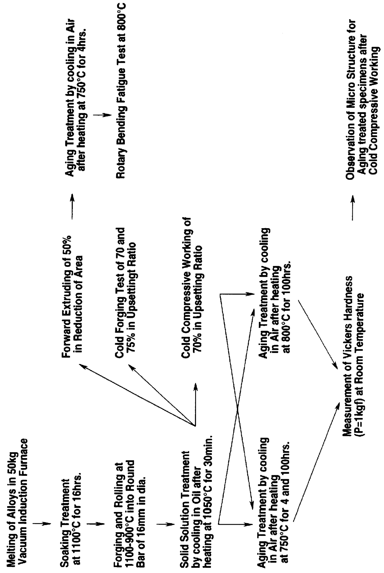
Alloys of 50 kg having chemical compositions as shown in Table 1 were melted respectively in a vacuum induction furnace, thereby obtaining ingots, and properties of the respective alloys were examined according to the process shown in FIG. 1.

First of all, a round bar specimen of 8 mm in diameter was cut out from a bottom portion of each of ingots after subjecting the ingots to soaking treatment at a temperature of 1100.degree. C. for 16 hours, and hot workability of the respective alloys were examined by high temperature-high speed tensile test using the specimens.

TABLE 1 __________________________________________________________________________ Alloy Chemical composition (wt %) No. C Si Mn P S Cu Ni Co Cr Mo W V Nb + Ta Al __________________________________________________________________________ Invention 1 0.032 0.21 0.21 -- -- 0.97 32.3 -- 16.0 -- -- -- 0.25 2.15 alloy 2 0.051 0.18 0.16 -- -- 2.06 32.0 -- 15.9 -- -- -- 0.28 1.85 3 0.020 0.04 0.06 -- -- 3.98 27.1 -- 12.8 -- -- --...

example 2

Alloys of 50 kg having chemical compositions as shown in Table 3 were melted respectively in a vacuum induction furnace, thereby obtaining ingots, and properties of the respective alloys were examined according to the process as shown in FIG. 2.

TABLE 3 __________________________________________________________________________ Alloy Chemical composition (wt %) No. C Si Mn P S Cu Ni Fe Co Cr W Mo Nb + Ta Al __________________________________________________________________________ Invention 20 0.012 0.21 0.20 -- -- 0.52 32.1 47.4 -- 16.4 -- -- 0.35 2.35 alloy 21 0.083 0.22 0.20 -- -- 3.99 31.8 43.6 -- 16.0 -- -- 1.86 0.78 22 0.048 0.19 0.22 -- -- 4.11 42.2 27.8 -- 21.2 -- -- 0.83 2.10 23 0.033 0.22 0.21 -- -- 2.07 32.2 47.1 -- 13.4 -- 1.52 0.44 2.27 24 0.046 0.21 1.21 -- -- 2.02 31.8 47.4 -- 13.5 1.44 -- 0.51 2.25 25 0.050 0.22 0.20 -- -- 1.99 31.8 46.2 -- 14.4 0.98 0.56 0.56 2.11

26 0.031 0.18 0.17 -- -- 1.94 28.7 47.1 2.11 15.9 -- -- 0.82 2.08 27 0.042 0.20 0.18 -- -- 2.06 31.9 44.7 ...

example 3

Alloys of 50 kg having chemical compositions as shown in Table 5 were melted in a vacuum induction furnace and cast into ingots, respectively.

TABLE 5 __________________________________________________________________________ Ti / Al Al + Ti + Alloy Chemical composition (wt %) (at M- Nb + Ta No. C Si Mn Cu Ni Co Cr W Mo Nb + Ta Al Ti B Mg + Ca Fe %) value (at __________________________________________________________________________ %) 1 0.051 0.21 0.20 0.98 32.1 -- 16.4 -- -- 0.82 1.15 2.29 0.0030 -- 45.8 1.48 0.934 5.34 2 0.083 0.22 0.20 4.05 31.8 -- 16.0 -- -- 0.78 1.64 1.76 0.0032 0.003 43.5 0.60 0.928 5.71 3 0.048 0.19 0.22 2.20 31.9 -- 16.3 -- -- 0.88 1.98 1.49 0.0050 -- 45.0 0.42 0.936 6.11 4 0.033 0.22 0.21 2.07 32.2 -- 14.1 0.99 0.56 1.52 2.27 0.51 0.0027 -- 45.3 0.13 0.914 5.91 5 0.046 0.21 0.21 1.04 42.2 -- 16.3 -- -- 0.81 0.85 2.8 0.0031 -- 35.5 1.86 0.923 5.53 6 0.050 0.22 0.20 1.99 31.8 -- 15.9 -- -- 0.83 2.36 0.84 0.0040 -- 45.8 0.20 0.932 6.10 7 0.031 0.18 0.19 1.94 25....


PUM

PropertyMeasurementUnit
Fractionaaaaaaaaaa
Fractionaaaaaaaaaa
Fractionaaaaaaaaaa

Abstract

A method for producing an exhaust valve is described, comprising subjecting a raw material of a specified heat resisting alloy to solid solution treatment; forming a head portion of the exhaust valve from the solution treated raw material through cold working or warm working; joining a stem portion made of martensitic heat resisting steel to said head portion of the exhaust valve; and subjecting the head portion and the stem portion joined with each other to aging treatment.

Description

BACKGROUND OF THE INVENTION1. Field of the InventionThis invention relates to a heat resisting alloy especially excellent in cold workability and suitable to be used for exhaust valves of automotive engines, and a method for producing the exhaust valves using the above-mentioned heat resisting alloy.2. Description of the Prior ArtHeretofore, as a material for an exhaust valve of automotive engines or so, high Mn austenitic heat resisting steel JIS SUH 35 (Fe-9Mn-21Cr-4Ni-0.5C-0.4N) or Ni-based super alloy JIS NCF 751 (Ni-15.5-Cr-0.9Nb-1.2Al-2.3Ti-7Fe-0.05C) has been used, for example.Although the aforementioned Ni-based super alloy is an alloy excellent in high-temperature strength, high-temperature oxidation resistance and high-temperature corrosion resistance, there is a problem in the cost since the alloy contains expensive Ni as much as a little more than 70 wt %.Accordingly, an approach for decreasing the amount of expensive Ni has been carried out, and alloys containing Ni of ...

Claims


Application Information

Patent Timeline
IPC IPC(8): C22C38/38C22C38/48C22C38/42C22C30/00C22C38/06C22C38/50C21D6/02F01L3/02C21D9/50
CPCC21D6/02C22C30/00C22C38/06C22C38/38C22C38/42C22C38/48C22C38/50F01L3/02C21D9/50
Inventor UETA, SHIGEKINODA, TOSHIHARUOKABE, MICHIO
Owner DAIDO STEEL CO LTD
Features
  • Generate Ideas
  • Intellectual Property
  • Life Sciences
  • Materials
  • Tech Scout
  • Unparalleled Data Quality
  • Higher Quality Content
  • 60% Fewer Hallucinations
Learn More