Fabrication of metal fuse design for redundancy technology having a guard ring

a technology of metal fuse and guard ring, which is applied in the direction of electrical equipment, semiconductor devices, semiconductor/solid-state device details, etc., can solve the problems of reducing circuit reliability and yield, difficult to accurately etch the fuse opening to a precise depth, and difficulty in accurately making the fuse opening

Inactive Publication Date: 2000-08-08
TAIWAN SEMICON MFG CO LTD
View PDF7 Cites 117 Cited by
  • Summary
  • Abstract
  • Description
  • Claims
  • Application Information

AI Technical Summary

Problems solved by technology

As the number of metal layers and inter metal dielectric layers (IMD) increases, it is more difficult to accurately etch the fuse opening to a precise depth.
Moreover, because of the additional inter metal dielectric layers, the dielectric layer uniformity within wafer and wafer to wafer creates difficulty in accurately making fuse openings.
Another important challenge is to improve the reliability and yields of the semiconductor devices surrounding openings in insulating layers, such as openings over fusible links.
A problem with openings is that moisture and other contaminants can diffuse from the openings into the device areas thus reducing circuit reliability and yields.
However, the first and second layers are not bonded to each other and therefore allow moisture to diffuse to the active devices.
Unfortunately, the problem of contaminants diffusing to the semiconductor devices through the fuse window still exists and an improved structure / method of forming a guard ring is still needed.

Method used


Image

  • Fabrication of metal fuse design for redundancy technology having a guard ring
  • Fabrication of metal fuse design for redundancy technology having a guard ring
  • Fabrication of metal fuse design for redundancy technology having a guard ring

Examples


example 1-- fuse

Example 1--Fuse Formed in Metal 2 Layer

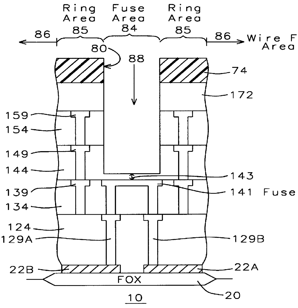
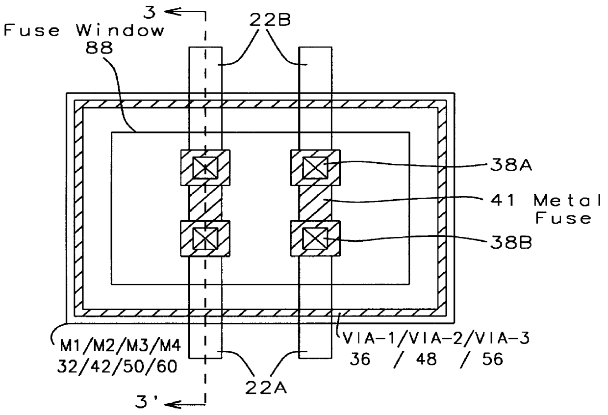
A preferred embodiment of the invention is shown in FIGS. 2 and 3. The preferred embodiment forms the metal fuse 41 in the second metal layer (M2) and shows a guard ring formed from the 2nd, 3rd and 4th metal layers.

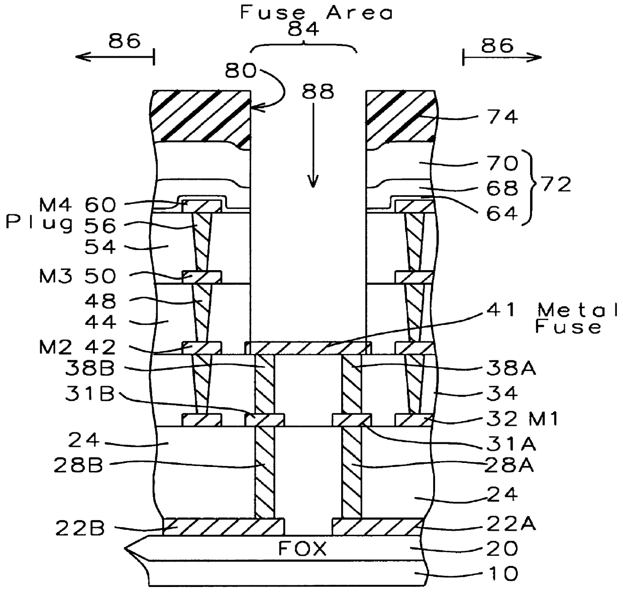
FIG. 3 shows a cross section of a preferred embodiment where the metal fuse 44 is formed from the second metal layer (M2). FIG. 2 shows a top down view of the guard ring and metal fuse.

As shown in FIG. 3, an isolation region 20 is formed over at least a fuse area 84 in a substrate 10.

Next, a first polysilicon line 22A and a second polysilicon line 22B are formed on the isolation region 20 partially across the fuse area. The polysilicon lines preferably have a thickness in a range of between about 300 and 3000 .ANG.. The polysilicon layer 22 be formed of other materials, such as polycides, silicides, Ti Silicide, etc.

A first insulating layer 24 (interlevel dielectric (ILD)) is formed over the first polysilicon line 22A, the second po...


PUM


Abstract

A method of fabricating a metal guard ring (e.g., 139 149 159) around for a metal fuse 141 and fuse opening 88. The metal fuse 41 is formed from a second metal layer (M2) (or M3 or M4, etc.) and is connected to an underlying polysilicon layer 22 by fuse interconnections 129A 129B. The method comprises: a) forming a first polysilicon line 22A and a second polysilicon line 22B over at least the fuse area 84 insulated (e.g., 20) from a substrate 10; b) forming one or more levels of fuse interconnects (129A 129B) electrically connected to the first polysilicon line 22A and the second polysilicon line 22B; the fuse interconnects 129A 129B passing through vias in one or more insulating layers 24 34; c) simultaneously forming a metal fuse 141 connecting the polysilicon interconnects 129A 129B over the fuse area 84 and forming a first guard ring 139 around a fuse area 84; d) forming an dielectric layer 144 over the metal fuse 141 and the first guard ring 139; e) forming a guard ring around the fuse areas 84; the guard ring composed of a plurality of metal wiring layers 149 159 formed on and through vias in a plurality of dielectric layers 144 154; and f) forming a fuse opening 88 through at least a portion of the plurality of dielectric layers 144 154 172 in the fuse area.

Description

BACKGROUND OF INVENTION1) Field of the InventionThis invention relates generally to fabrication and design of metal fuses for semiconductor devices and particularly to the fabrication of a metal fuse having a guard ring composed of metal layers and vias.2) Description of the Prior ArtFuses can be used to rewire memory and logic circuits. For example, in dynamic or static memory chips, defective memory cells may be replaced by blowing fuses associated with the defective cells, and activating a spare row or column of cells. This circuit rewiring using fusible links allows considerable enhanced yields and reduces the production costs. Also, logic circuits may also be repaired or reconfigured by blowing fuses. For example, it is common to initially fabricate a generic logic chip having a large number of interconnected logic gates. Then, in a final processing step, the chip is customized to perform a desired logic function by disconnecting the unnecessary logic elements by blowing the fu...

Claims


Application Information

Patent Timeline
Patent Type & Authority Patents(United States)
IPC IPC(8): H01L23/52H01L23/525
CPCH01L23/5258H01L2924/0002H01L2924/00
Inventor SHIH, CHENG-YEHHUANG, JENN MING
Owner TAIWAN SEMICON MFG CO LTD
Why Eureka
Try Eureka