Fiber-reinforced composite materials structures and methods of making same

Inactive Publication Date: 2000-08-15
ALBANY ENGINEERED COMPOSITES
View PDF8 Cites 127 Cited by
  • Summary
  • Abstract
  • Description
  • Claims
  • Application Information

AI Technical Summary

Problems solved by technology

Typically, however, they it will not be of the same materials or have comparable physical, chemical thermal or other properties, since a usual objective sought in using composites in the first place is to achieve a combination of characteristics in the finished product that is not attainable through the use of one constituent material alone.
However, when tension is applied to the cured panel or the skin of the composite structure, loads at unacceptably low values resulted in "peel" forces which separate the stiffening element from the panel at their interface since the effective strength of the join is that of the matrix material and not of the adhesive.
Therefore, junctures relying on matrix material per se for their strength are in

Method used


Image

  • Fiber-reinforced composite materials structures and methods of making same
  • Fiber-reinforced composite materials structures and methods of making same
  • Fiber-reinforced composite materials structures and methods of making same

Examples


examples

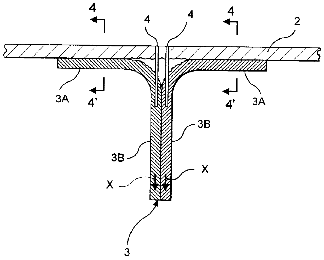
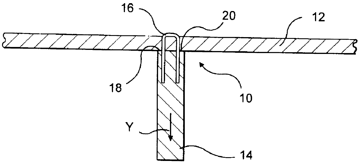
Five test samples were constructed substantially as disclosed in U.S. Pat. No. 5,429,853 as illustrated in FIG. 1 attached. Five more were constructed substantially in accordance with the present invention and as illustrated in FIG. 2 attached. In all cases, substantially identical jigs and other appliances were attached to all of samples in order to adapt them to the testing apparatus and, as nearly as possible, to isolate the test results from factors extraneous to determining the strength of the joins per se in each. The samples were of substantially identical size and dimensions, and were made using identical carbon yams for reinforcing and joining, and epoxy matrix materials of substantially the same quality, dimensions and other compositional and physical properties, and the tests were conducted under substantially identical test conditions. The stitching was oriented in the direction of the long axes of the reinforcing ribs and was of the same stitch density in all samples. S...


PUM

PropertyMeasurementUnit
Angleaaaaaaaaaa
Massaaaaaaaaaa
Massaaaaaaaaaa

Abstract

Reinforcement preforms and methods for making same for use in fiber-reinforced composite materials structures are disclosed, in which the reinforcement preforms comprise first and second reinforcement preform elements which include strength reinforcement fibers that are in desired directional orientation. The first element has a cross-fiber surface which extends transverse of its constituent strength reinforcement fibers and is in contacting juxtaposition to a selected surface region of the second element, forming an abutment therebetween. Abutment strength reinforcing fibers, which may optionally be introduced in situ by a continuum of fibers, such as a yarn or thread, extend through at least a portion of said second element and its said selected surface region, the abutment, said cross-fiber edge surface, and into the first element substantially in the direction of orientation to its constituent strength fibers to which its cross-fiber surface is transverse.

Description

BACKGROUND OF INVENTIONThe use of reinforced composite materials to produce structural components is now widespread, particularly in applications where their desirable characteristics are sought of being light in weight, strong, tough, thermally resistant, self-supporting and adaptable to being formed and shaped. Such components are used, for example, in aeronautical, aerospace, satellite, battery, recreational (as in racing boats and autos), and other applications.As is known in the prior art, typically such components consist of reinforcement materials embedded in matrix materials. The reinforcement component may be made from materials such as glass, carbon, ceramic, aramid (e.g., "KEVLAR"), polyethylene, and / or other materials which exhibit desired physical, thermal, chemical and / or other properties, chief among which is great strength against stress failure. Through the use of such reinforcement materials which ultimately become a constituent element of the completed component, ...

Claims


Application Information

Patent Timeline
IPC IPC(8): B29C70/24B29C70/10B32B5/00
CPCB29B11/16B29C65/564B29C66/112B29C66/114B29C66/721B29C70/24B29C66/43441Y10T428/24174B29L2031/003Y10T428/24033B29C66/7212B29C66/71B29C66/72141Y10T428/249923B29K2307/04B29K2063/00B29K2031/00B29K2067/00B32B5/12
Inventor BURGESS, KEITH E.
Owner ALBANY ENGINEERED COMPOSITES
Why Eureka
Try Eureka