System for coding voice signals to optimize bandwidth occupation in high speed packet switching networks

a voice signal and bandwidth optimization technology, applied in the field of coding voice signals, can solve the problems of increasing bandwidth consumption of corresponding traffic, requiring more connectivity, and requiring more deterministic and logical connections, and achieve the effect of improving the subjective quality of received voice signals, convenient noise shaping, and good signal-to-noise ratio

Inactive Publication Date: 2000-08-15
IBM CORP
View PDF6 Cites 88 Cited by
  • Summary
  • Abstract
  • Description
  • Claims
  • Application Information

AI Technical Summary

Benefits of technology

A still further object of this invention is to provide a multirate voice encoding system with which random switching from one rate of operation to another would not disturb decoding operations.
Another object of this invention is to provide a multirate voice encoder with a good Signal-to-Noise Ratio at higher rate as well as convenient noise shaping improving subjective qu...

Problems solved by technology

Accordingly, due to the variety of users' profiles and distributed applications, the corresponding traffic is becoming more and more bandwidth consuming, non-deterministic and requiring more connectivity.
The fundamental challenge for high speed networks is to minimize the processing time and to take full advantage of the high speed/low error rate technologies.
The drawback, however, is that packet switching introduces delays and jitters which might be detrimental for transmission of isochronous data, like video or voice.
From a cost efficiency standpoint, the network bandwidth occupation should be optimized, but due to the random nature of any network traffic this goal is far from being easy to achieve.
But this is not the case with Real Time (RT) traffic, like video or voice (speech)...

Method used


Image

  • System for coding voice signals to optimize bandwidth occupation in high speed packet switching networks
  • System for coding voice signals to optimize bandwidth occupation in high speed packet switching networks
  • System for coding voice signals to optimize bandwidth occupation in high speed packet switching networks

Examples


Embodiment Construction

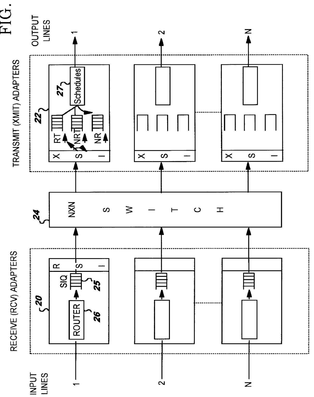
As already mentioned, the existing high speed digital network nodes (see FIG. 2) have been designed to optimize network bandwidth occupation by enabling dynamic regulation of flow traffic. To that end, the nodes have been provided with flow control systems for controlling committed traffic with guaranteed delivery to the connected user, and for controlling so-called excess traffic which might be discarded. Should the connection path suffer congestion at any moment, means are known to adjust the bandwidth assigned to said excess traffic. In that case, if necessary, packets belonging to said excess traffic might be discarded.

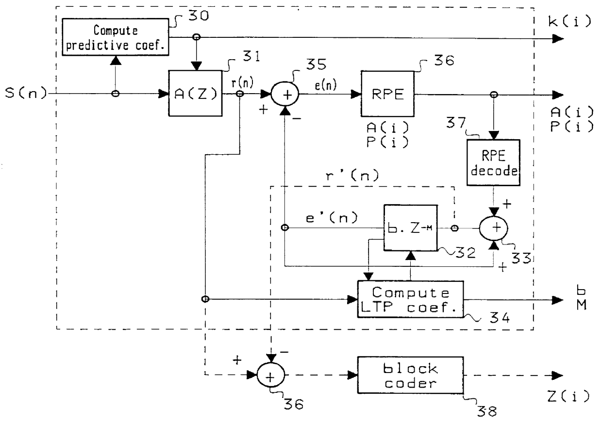
This kind of network architecture should enable multirate speech transmission without any significant modification of the network, as long as the speech coder used enables building up output frames of coded signal which could be split into discardable frame portions and non-discardable frame portions. Another requirement is that random packet discarding throughout...


PUM


Abstract

A system for coding voice signal to optimize bandwidth occupation in a High Speed Packet Switching network while ensuring best voice transmission quality. The voice signal is first encoded using a conventional GSM like RPE/LTP coder providing first sub-frames of coded signal and tagging these first sub-frames as being non-discardable. In addition, a convenient difference between an RPE/LTP provided signal and a corresponding synthesized image is performed (see 36) and is also block encoded into second sub-frames which second sub-frames are tagged as being discardable sub-frames. Said second sub-frames when concatenated to corresponding first sub-frames provide so-called multirate frames. Then, when transmitting said multirate frames over the High Speed packet switching network, dropping discardable tagged data enables solution network congestion situations in any network node and at random with no significant disturbing effect over the voice communication operation.

Description

This invention deals with a system for coding voice signals to optimize bandwidth occupation in packet switching communication networks, and more particularly for implementing said network optimization through use of improved multirate voice coding.Modern digital networks are made to operate in a multimedia environment and interconnect, upon request, a very large number of users and applications through fairly complex digital communication networks.Represented in FIG. 1 is an example showing the complexity of presently operating networks. Represented is a backbone network (100), e.g., an Asynchronous Transfer Mode (ATM) network, with multiple end users attached to said network. Some users are directly attached to the ATM network. Others are attached to the ATM network via an access network (102). As represented in FIG. 1, the system does operate in a multimedia environment by having to transport pure data as well as video and audio information, the latter being provided by PBX or CX...

Claims


Application Information

Patent Timeline
IPC IPC(8): G10H1/26G10H1/00G10H1/053
CPCG10H1/0066G10H1/26G10H2230/201G10H2240/251
Inventor GALAND, CLAUDELEBIZAY, GERALDMENEZ, JEANPUCCI, BERNARDRICHTER, GERARDROSSO, MICHELE
Owner IBM CORP
Why Eureka
Try Eureka