Lens and associatable flow cell

a flow cell and associative technology, applied in the field of biosensors, can solve the problems of inability to reliably seal, interfere with the desired analysis, and the waveguide portion of integrally formed or molded biosensors may exhibit deformation upon fabrication, and achieve the effect of improving the antigen-binding capacity (agbc) of immobilized antibodies, high mobility, and high degree of non-specific binding

Inactive Publication Date: 2000-08-22
UNIV OF UTAH RES FOUND
View PDF7 Cites 134 Cited by
  • Summary
  • Abstract
  • Description
  • Claims
  • Application Information

AI Technical Summary

Benefits of technology

One immobilization chemistry is based on physical adsorption of antibodies to the waveguide. In one method, an antibody is briefly exposed to acidic conditions just prior to immobilization. It has been shown that this acid pretreatment step improves the antigen-binding capacity (AgBC) of immobilized antibodies by up to 3-fold in some cases. This immobilization chemistry is relatively simple and compatible with gasketed multi-well coating tray or liquid jet printing technology, but in some cases it exhibits a higher degree of non-specific binding than other methods.
The other two immob

Problems solved by technology

Unfortunately, the waveguide portion of integrally formed or molded biosensors may exhibit deformation upon fabrication, or warping during storage or tem

Method used


Image

  • Lens and associatable flow cell
  • Lens and associatable flow cell
  • Lens and associatable flow cell

Examples


example i

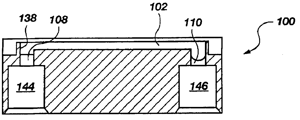
A waveguide with integrated lenses, such as that depicted in FIGS. 6 & 7, was injection molded in a clean environment from a transparent, general purpose polystyrene. The waveguide had a length of 38 mm, and a width of 25 mm. The thickness 176 of the planar surface 170 was a consistent 0.5 mm. The ridge or "shelf" had a height of 1.3 mm. The front lens and rear lens had bottom edges co-planar with their respective centers of curvature. The front lens horizontal angle 262 was about 15.degree.. The rear lens horizontal angle 264 was about 19.degree.. The radii of curvature of the front and rear lenses were about 3.2 mm and 1.6 mm respectively. The mean angle .theta. of the front lens was 21.degree.. The mean angle of the rear lens was about 24.degree..

example ii

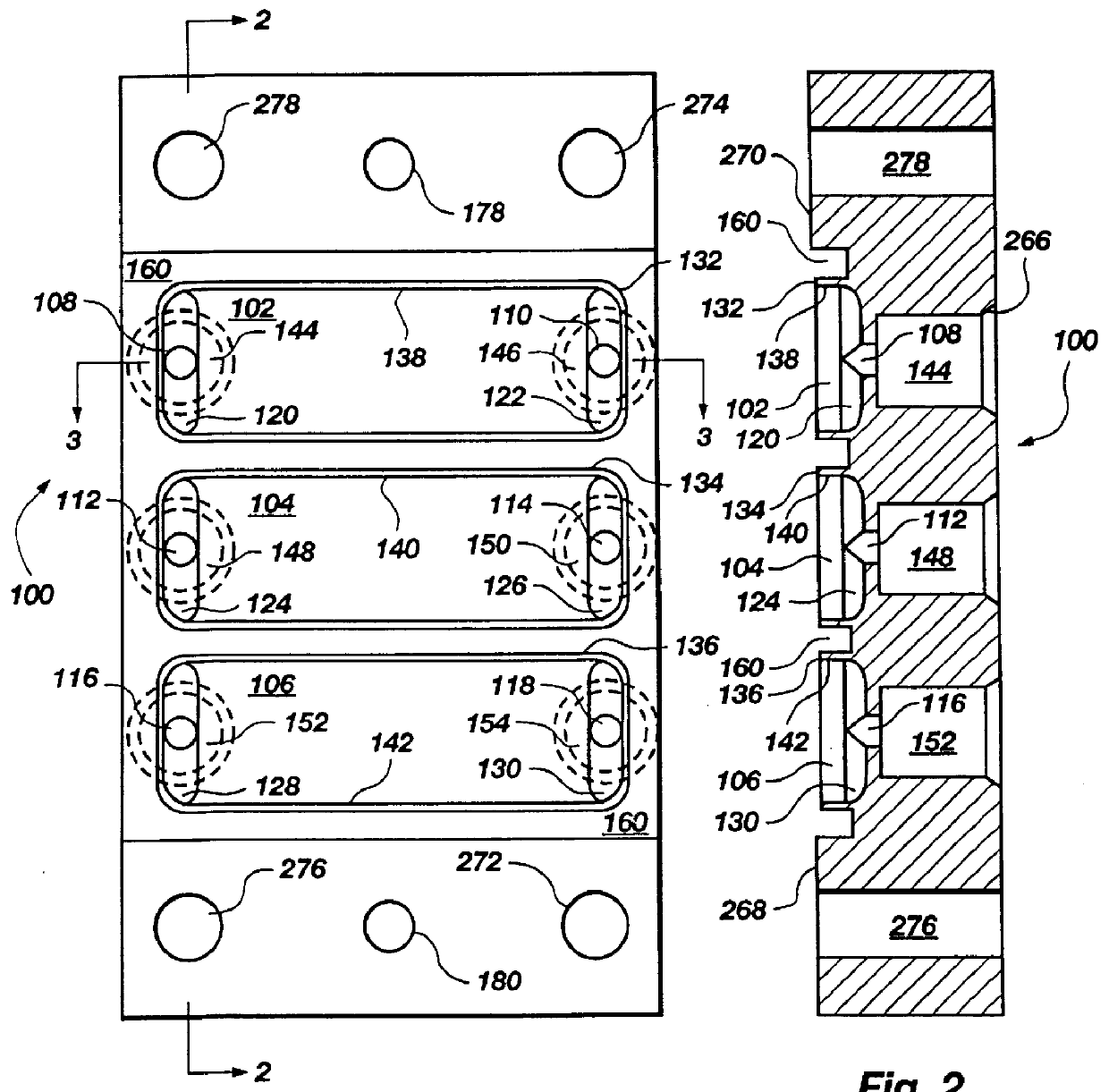
A flow cell top, such as that depicted in FIGS. 1-3, and 8, was made of hard black anodized 6061-T6 aluminum. It contained three reservoirs each of which had a 0.25 mm (0.010 in.) thick wall surrounding it, a flat floor in middle, two half-capsule shaped recesses at either end 1.6 mm (1 / 16 in.) in width, and ports 1.6 mm (1 / 16 in.) in diameter running into the center of each recess. The ports opened into a #10-32 (standard thread, not NPT) connector which ran out to the opposite face of the flow cell and was 5.1 mm (0.200 in.) deep. A 90.degree. countersink 266 (FIG. 2) was given at the surface of the port connector (a plastic barbed tubing connector screwed into the port connector and sealed on the countersink). On both sides of the array of reservoirs were two raised platforms which were referred to as lands 268, 270. Each land had three holes running through the thickness of the part. The four #31 clamping holes 272, 274, 276, 278 were formed (i.e. drilled through). The two apert...

example iii

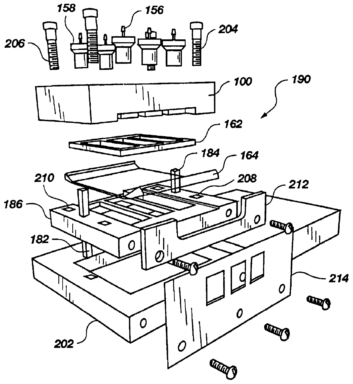
A gasket 162, such as that depicted in FIGS. 4, 5, and 11, was made as a composite structure laminated from 1.6 mm (1 / 16 in.) silicone rubber sheeting and 0.076 mm (0.003 in.) self-adhesive FEP film (total thickness: 1.676 mm (0.066 in.) nominal). Its outer dimensions were about 25 mm (1 in.) by 25.40 mm (1.000 in.) and it had three internal openings which corresponded to the flow cell reservoirs. The gasket was produced using a waterjet cutter and was seated on the flow cell such that the FEP layer faced away from the flow cell surface.


PUM


Abstract

PCT No. PCT/US97/04398 Sec. 371 Date Sep. 18, 1998 Sec. 102(e) Date Sep. 18, 1998 PCT Filed Mar. 19, 1997 PCT Pub. No. WO97/35176 PCT Pub. Date Sep. 25, 1997Improvements in a biosensor of the type having reservoirs or wells for analyzing a biological liquid are disclosed. A biosensor (190) includes a waveguide (164) placed between a plurality of members such as plates (100, 186), at least one of the members (100) being formed to define the walls (132, 134, 136) of the reservoirs where the liquid is biologically analyzed. The walls of the reservoirs are made of an inert, opaque material such as a metal. Although the biosensor may include a gasket (162), the gasket is associated with the members and waveguide in such a way (e.g. by recessing the gasket into a channel formed into a metal plate) so that the gasket does not form any significant portion of the reservoir wall. Waveguides of varying composition (e.g. plastic, quartz or glass) may be associated with the members to form the biosensor. The metal plate of the biosensor has input and output ports for infusing, draining, or oscillating the liquid to be analyzed in the reaction reservoir. Also disclosed is a sled-shaped waveguide associated with a rear lens to couple light out of the waveguide to serve as a quality control measure thus insuring that the biosensor is properly placed and that the light is working.

Description

This invention relates generally to components of a diagnostic apparatus, and more particularly to an improved biosensor having a lens ("waveguide") and associated flow cell.International Application No. PCT / US94 / 05567 (International Publication No. 94 / 27137, published Nov. 24, 1994) to the University of Utah Research Foundation discloses an apparatus for multi-analyte homogeneous fluoroimmunoassays. In one embodiment, the application discloses an apparatus which uses a biosensor having a planar waveguide sandwiched, with an associated gasket, between two plates (FIGS. 3A-3C of Internat'l Publ. No. 94 / 27137). The inner edges of the gaskets serve as walls for a reaction reservoir or well. Fluorescence-emitting tracer molecules are bound to the waveguide surface and are excited by an evanescent field penetrating into the adjacent solution from a light beam propagated within the waveguide, the beam being introduced at, for example, a front end of the waveguide. In the reaction reservoi...

Claims


Application Information

Patent Timeline
IPC IPC(8): G01N21/03G01N21/05G01N21/64G01N33/543G01N33/552G02B6/00G02B6/32
CPCG01N21/0303G01N2021/058
Inventor HERRON, JAMES N.CHRISTENSEN, DOUGLAS A.POLLAK, VICTOR A.MCEACHERN, RICHARD D.SIMON, ERIC M.
Owner UNIV OF UTAH RES FOUND
Why Eureka
Try Eureka