Piston pump

a technology of piston pump and piston cylinder, which is applied in the direction of positive displacement liquid engine, liquid fuel engine, braking system, etc., can solve the problems of large amount of material to be removed from the stepped piston, high cost, and high cos

Inactive Publication Date: 2000-08-29
ROBERT BOSCH GMBH
View PDF5 Cites 35 Cited by
  • Summary
  • Abstract
  • Description
  • Claims
  • Application Information

AI Technical Summary

Benefits of technology

The piston pump of the invention has the advantage over the prior art that the stepped piston can be produced very economically and has a marked cost advantage over a one-piece turned part or a stepped piston divided into two parts, that is, a piston rod and a piston cylinder. Thus, for the piston pump of the invention, with the advantage, dictated by the stepped nature of the pump piston, of higher pumping capacity even at low temperatures, the market for more-economical brake systems for vehicles of the lower price class is also opened up, which can help improve the braking performance in this class.The invention is described in further detail in the ensuing description in terms of exemplary embodiments shown in the drawing. Shown are:FIG. 1, a fragmentary longitudinal section through a piston pump for a vehicle brake system;FIG. 2, an enlarged view of detail II in FIG. 1 for a modified piston pump;FIGS. 3a and 3b, a longitudinal section of the bush, press-fitted onto the solid cylinder, to illustrate the stepped piston of the piston pump of FIG. 2, in accordance with two exemplary embodiments.

Problems solved by technology

Such a pump piston, because of the expense for machining, is very cost-intensive.
In order to obtain a clearly apparent distinction between these two diameters, a great deal of material has to be removed from the stepped piston, which involves considerable labor.
This two-part nature of the pump again entails high production costs, especially since the piston cylinder and the piston rod require separate guides for their axial motion.

Method used


Image

  • Piston pump
  • Piston pump
  • Piston pump

Examples


Embodiment Construction

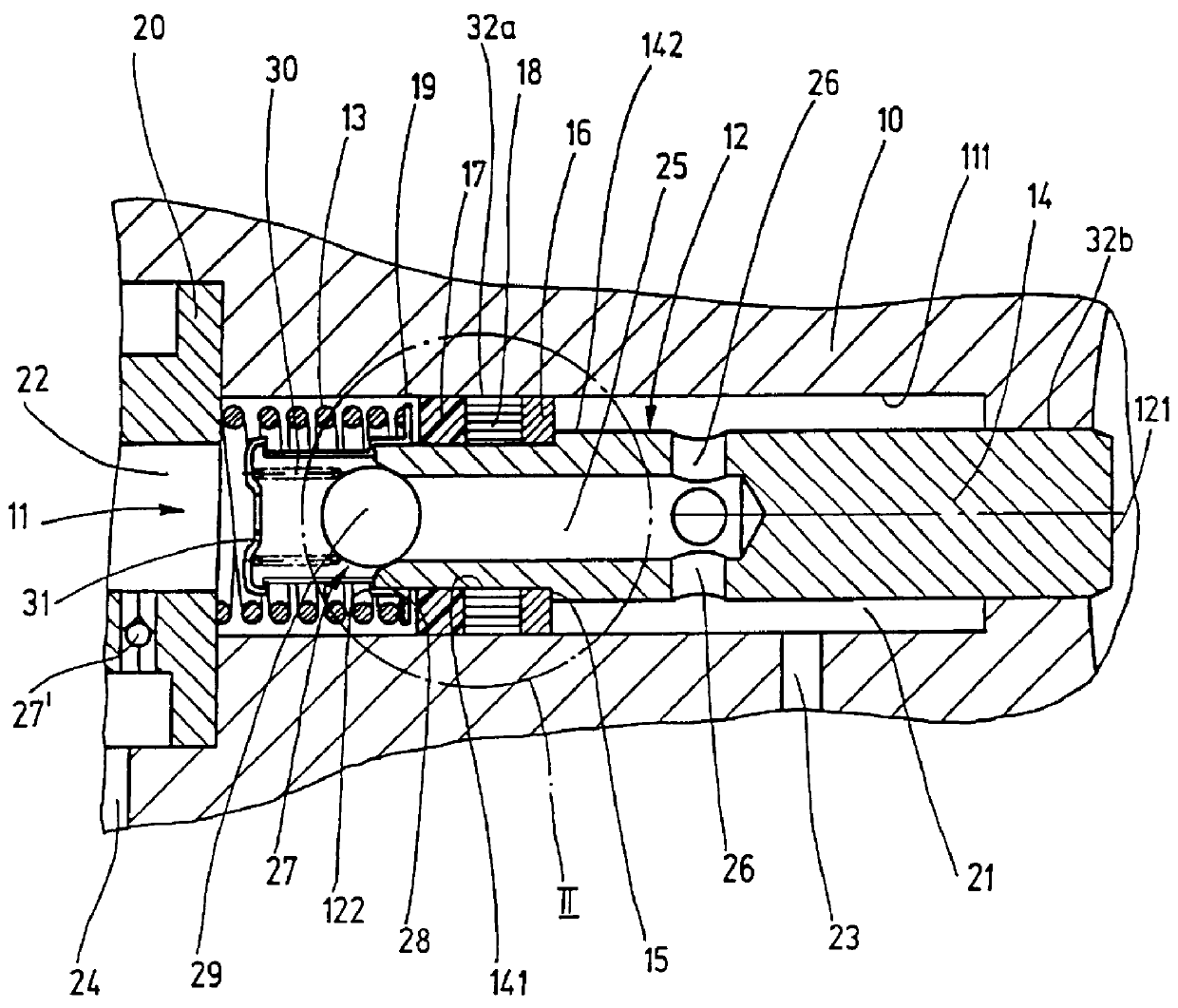
The piston pump shown in fragmentary longitudinal section in FIG. 1 for pumping hydraulic fuel is intended particularly as a pump in a vehicle brake system and is used for controlling the pressure in wheel brake cylinders. Depending on the type of brake system, the abbreviations ABS, ASR, FDR and EHB are used for such brake systems. In the brake system, the pump serves for instance to feed back brake fluid from one or more wheel brake cylinders to a master cylinder (ABS), and / or for pumping brake fluid out of a supply container into one or more wheel brake cylinders (ASR, FDR and EHB). The pump is required for instance in a brake system with wheel slip control (ABS or ASR) and / or in a brake system serving as a steering aide (FDR) and / or in an electrohydraulic brake system (EHB). With the wheel slip control (ABS or ASR), for instance, locking of the wheels of the vehicle during a braking event when strong pressure is exerted on the brake pedal can for instance be prevented (ABS), and...


PUM

PropertyMeasurementUnit
diameteraaaaaaaaaa
pressureaaaaaaaaaa
circumferenceaaaaaaaaaa

Abstract

PCT No. PCT / DE97 / 01101 Sec. 371 Date May 18, 1998 Sec. 102(e) Date May 18, 1998 PCT Filed Jun. 3, 1997 PCT Pub. No. WO98 / 12434 PCT Pub. Date Mar. 26, 1998A piston pump for pumping hydraulic fluid, especially for vehicle brake systems having a stepped piston axially displaceable in a pump space. The stepped piston in order to reduce the production costs comprises a cylinder of substantially constant outer diameter and a bush which is held axially nondisplaceably on the cylinder, by being press-fitted onto the cylinder. An elastomer seal is slipped onto a cylinder portion defined by the bush seals off the cylinder from the wall of the pump space and divides the pump space into two pump chambers of variable chamber volume.

Description

PRIOR ARTThe invention is based on a piston pump for pumping hydraulic fluid, particularly for vehicle brake systems.In a known piston pump of this type (German Patent Disclosure DE 44 07 978 A1), the stepped piston is produced as a one-piece turned part, in which a plurality of annular grooves are punched to make pump chambers and for receiving seals. Such a pump piston, because of the expense for machining, is very cost-intensive. The stepped piston has one region with a larger diameter and another region with a smaller diameter. In order to obtain a clearly apparent distinction between these two diameters, a great deal of material has to be removed from the stepped piston, which involves considerable labor. The stepped piston is also supported axially displaceably in the region of its smaller diameter. Because of this support, the stepped piston must also have good shape and surface quality in this region as well. Because the diameter of the stepped piston is reduced at this bear...

Claims


Application Information

Patent Timeline
Patent Type & Authority Patents(United States)
IPC IPC(8): B60T8/40F04B53/00F04B53/14F16J1/08
CPCB60T8/4031F04B53/143F05C2225/04Y10T137/7873
Inventor SCHULLER, WOLFGANGALAZE, NORBERT
Owner ROBERT BOSCH GMBH
Why Eureka
Try Eureka