Flexible non-contact wound treatment device with a single joint

a wound treatment device and flexible technology, applied in the field of wound treatment devices, can solve the problems of reducing the effectiveness affecting the orientation affecting the adaptability and adaptability of the wound cover, so as to achieve the effect of reducing the size of the attachment portion and reducing the footprint of the wound treatment devi

Inactive Publication Date: 2000-08-29
GEN ELECTRIC CAPITAL
View PDF86 Cites 200 Cited by
  • Summary
  • Abstract
  • Description
  • Claims
  • Application Information

AI Technical Summary

Benefits of technology

A significant advantage of the invention is the potential reduction in size of the attachment portion, providing a smaller footprint of the wound treatment device.

Problems solved by technology

The orientation of the wound cover is difficult to maintain when the wound treatment device is mounted on a highly curved part of a body.
While the wound treatment devices disclosed in the referenced PCT applications exhibit excellent adaptability in a surface that is parallel to the surface of the body portion where the wound treatment device is mounted, there is impairment of adaptability and disturbance of the orientation of the wound cover due to limited flexibility in the direction of a Z axis that is perpendicular to the surfaces.
and collapse the standoff in the wound treatment portion.
The collapse of the standoff of course alters the orientation of the wound cover with respect to the wound, possibly reducing the effectiveness of the wound treatment device.
Therefore, when a three-dimensional wound treatment device is curved around a lower leg, substantial stress results that may result in deformation of the shape of the wound treatment device, in some cases even causing the wound cover to contact the wound.

Method used


Image

  • Flexible non-contact wound treatment device with a single joint
  • Flexible non-contact wound treatment device with a single joint
  • Flexible non-contact wound treatment device with a single joint

Examples


first embodiment

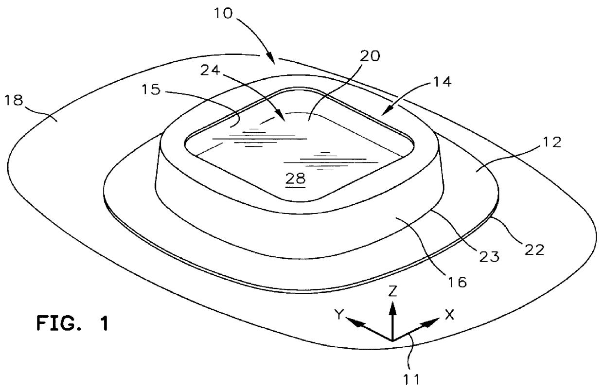
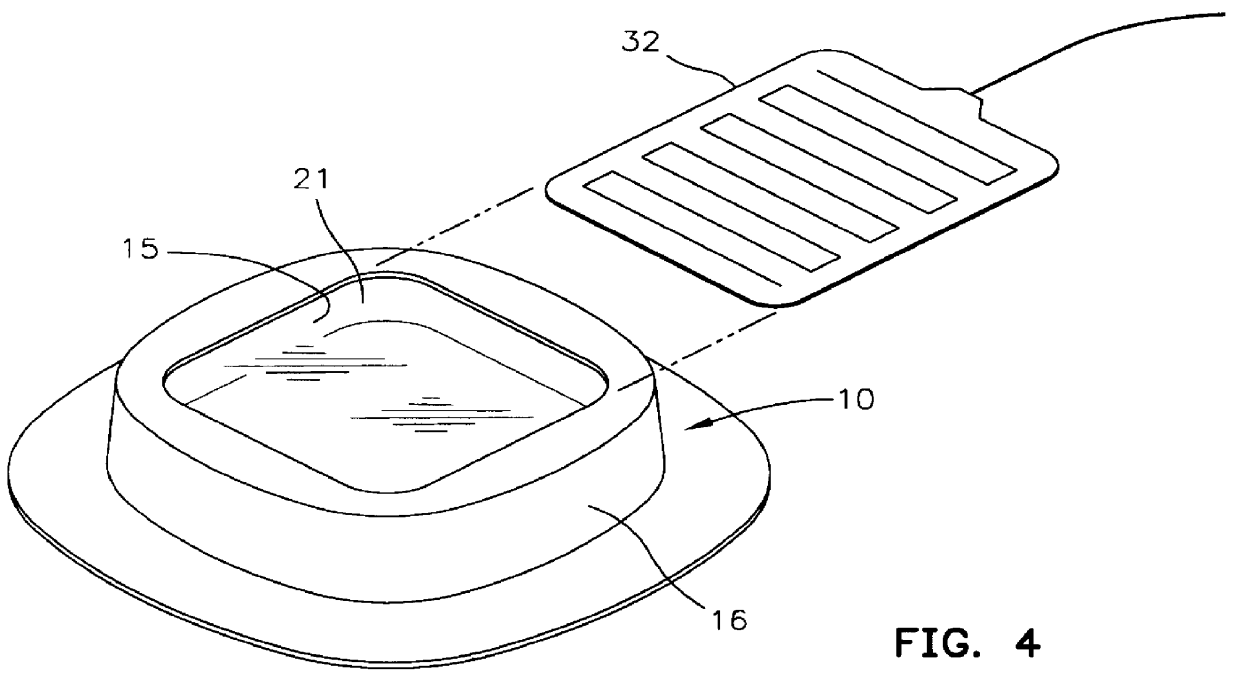
FIG. 5 is an exploded view of wound treatment device 10. Attachment portion 12 and transition portion membrane 36 are formed as a unitary composite shell 38. Composite shell 38 may be vacuum formed from closed cell polyolefin foams such as Volara-6AS, which is a polyethylene material as sold by Illbruck Inc., of Minneapolis, Minn. It should be apparent that many other materials may be substituted within the scope of the invention. Foam ring standoff 15 may be die cut from foam sheeting of a reticulated polyurethane foam. The absorbency of the foam as well as its mechanical properties can be tailored to the particular wound treatment application. For example, the foam standoff may be impregnated with a medicament such as an antibiotic, antifungal, or antimicrobial material. It may also be desirable to supply a deodorant material or nitric oxide releasing material from the foam standoff. Wound cover 20 and wound pocket 21 may be made from a thin film of polyethylene. In general, the c...

second embodiment

the transition portion 208 effectively allows articulation between the attachment portion 202 and the wound treatment portion 204. This is shown clearly in FIGS. 24 and 26A-26C. For example, in FIGS. 24 and 26B, the seal is in the location indicated by 208 / 220 in FIG. 25, essentially sealing an outer periphery of the upper surface 219 near the outer perimeter 223 to a corresponding outer periphery of the lower surface of the standoff 206. This permits the section of the attachment portion 202 extending to the inner perimeter 222 to articulate toward or away from the lower surface of the stand off 206. FIG. 26A shows attachment of the attachment portion 202 along the seam 208 / 222 to the lower surface of the standoff 206 near the inner perimeter 222, where the section of the attachment portion 202 extending to the outer perimeter 223 can articulate toward or away from the lower surface of the standoff 206. FIG. 26C shows attachment of the upper surface 219 to the lower surface of the ...

third embodiment

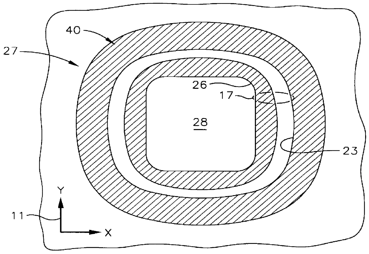
the transition portion 208 may be understood with reference to FIGS. 27-29. In these figures, the transition portion comprises a bridge of foam material spanning and providing a narrow passage through the space between the bottom surface of the standoff 206 and the top surface 219 of the attachment portion 202. The bridge 209 is provided during the manufacture of the standoff 206 and the attachment portion 202 as an integrated, unitary piece by, for example, molding open-celled plastic foam of the self-skinning type. In this case, the bridge 209 is provided for in the mold and forms concurrently and integrally with the standoff 206 and the attachment portion 202. After molding, an adhesive film layer with an attached release liner 112, 113 (both described above with respect to the wound treatment device illustrated in FIGS. 15-17) may be attached to the lower surface of the attachment portion for application of the wound treatment device to a skin surface. Manifestly, the bridge 209...


PUM


Abstract

A non-contact wound treatment device suitable for releasable attachment to a patient's skin surface over a selected wound area in a non-contact position relative to the selected wound area, the wound treatment device comprising an attachment portion suitable for releasable attachment with the patient's skin surface, having an inner perimeter for defining the selected wound area, a wound treatment portion with a wound cover and a support member supporting the wound cover, and a transition portion with a joint connecting the wound treatment portion to the attachment portion.

Description

TECHNICAL FIELDThis invention relates to a wound treatment device and, in particular, to a wound treatment device having a substantial portion of a wound cover that is in non-contact with a wound and capable of delivering heat to the wound. More particularly, the wound treatment device includes such a wound treatment device with a single joint that maximizes the ability of the wound treatment device to adapt to the contours and movements of a human body.BACKGROUND OF THE INVENTIONA novel mode of wound treatment is disclosed in detail in published PCT Applications WO 94 / 00090 and WO 96 / 15745, both owned in common with this application. This new treatment employs a non-contact wound treatment device that covers a wound, forming a treatment volume about and over the wound. An embodiment of such a wound treatment device may be characterized in having a plurality of parts, three of which are useful for the purpose of description. These three parts are an attachment portion, a wound treat...

Claims


Application Information

Patent Timeline
Patent Type & Authority Patents(United States)
IPC IPC(8): A61F13/02A61F13/00A61F15/00A61F7/00A61F7/08A61F7/02
CPCA61F7/007A61F15/008A61F2007/0071A61F2007/0078A61F2007/0088A61F2013/00165A61F2013/00182A61F2013/00195A61F2013/002A61F2013/00212A61F2013/00387A61F2013/00561A61F2013/00565A61F2013/0057A61F2013/0074A61F2013/00817A61F2013/00846A61F2013/0091A61F2013/00914A61F2013/00919
Inventor AUGUSTINE, SCOTT D.ROCK, JOHN P.
Owner GEN ELECTRIC CAPITAL
Why Eureka
Try Eureka