Spin-valve type thin film element and its manufacturing method

a technology of thin film elements and spin valves, applied in the field of spin valve type thin film elements, can solve the problems of difficult to allow, deteriorating reproduction characteristics, and inability to properly align magnetization,

Inactive Publication Date: 2000-09-05
TDK CORPARATION
View PDF9 Cites 7 Cited by
  • Summary
  • Abstract
  • Description
  • Claims
  • Application Information

AI Technical Summary

Problems solved by technology

However, magnetization can not be properly aligned along the X-direction because not only bias magnetic field but also inductive magnetic anisotropy is applied to the free magnetic layer 4, thereby deteriorating reproduction characteristic in that Barkhausen noises are liable to be generated.
However, it is thought to be difficult to allow the X-direction of the free magnetic layer 4 to be the direction of the easy axis of magnetization by the following reasons in the production method as described in the foregoing publication when the anti-ferromagnetic layer 10, which acquires an exchange coupling with the pinned magnetic layer 2 at the interface by applying a heat treatment under a magnetic field along the Y-direction (the height direction), is used.

Method used


Image

  • Spin-valve type thin film element and its manufacturing method
  • Spin-valve type thin film element and its manufacturing method
  • Spin-valve type thin film element and its manufacturing method

Examples


Embodiment Construction

Hysteresis loops of the free magnetic layers in respective spin-valve type film along the height direction were drawn using the spin-valve type films formed by two kinds of conventional production methods (Comparative Examples 1 and 2, and the spin-valve type film formed by the production method according to the present invention (Example). The experimental results are shown in FIG. 4 to FIG. 6.

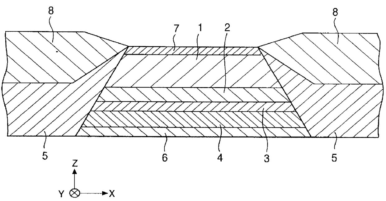
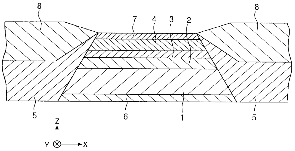
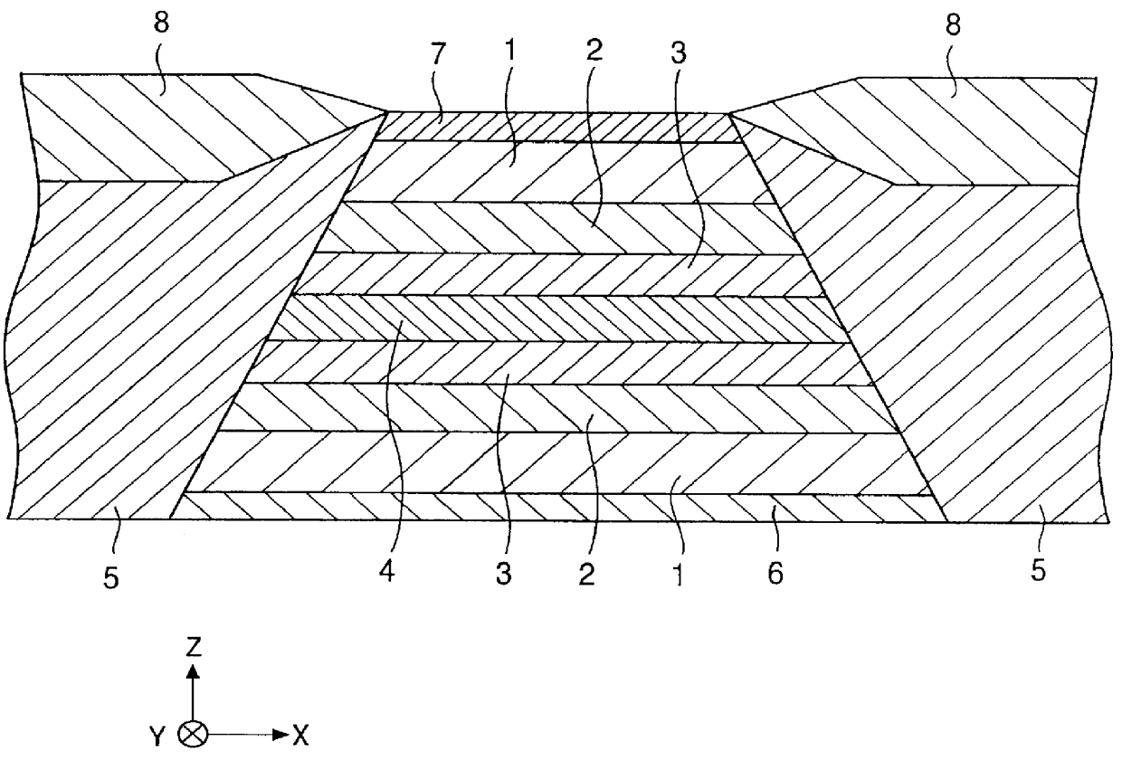
The constructions of respective spin-valve type films in Example and Comparative Examples 1 and 2 were the same as shown below:

Si / alumina (aluminum oxide) / underlayer: Ta (50) / free magnetic layer: Ni--Fe (70) / free magnetic layer: Co (10) / non-magnetic conductive layer: Cu (28) / pinned magnetic layer: Co (20) / antiferromagnetic layer: Pt--Mn (300) / protective layer: Ta (50)

The numerals for each layer described in the parenthesis indicate the film thickness represented in an Angstrom unit.

A Pt--Mn alloy film that can arise an exchange coupling by applying a heat treatment was used for the antiferrom...


PUM

PropertyMeasurementUnit
coercive forceaaaaaaaaaa
angleaaaaaaaaaa

Abstract

The object of the present invention is to solve the problems that inductive magnetic anisotropy of the free magnetic layer can not be directed along the track width direction because all the layers of the antiferromagnetic layer, pinned magnetic layer and free magnetic layer are deposited by applying a magnetic field along the height direction or, although the free magnetic layer is deposited while applying a magnetic field along the track width direction, the other layers are also deposited while applying a magnetic field along the height direction. The problems described above can be solved by forming the antiferromagnetic layer out of an antiferromagnetic material that can cause an exchange coupling by a heat treatment, and by depositing the antiferromagnetic layer, pinned magnetic layer and free magnetic layer at room temperature while applying a magnetic field along the X-direction, followed by a heat treatment. The procedure above enables inductive magnetic anisotropy of the free magnetic layer to be properly aligned along the X-direction prior to depositing the hard vias layer.

Description

1. Field of the InventionThe present invention relates to a so called spin-valve type thin film element in which electric resistance is changed by the relation between the direction of magnetization of a pinned magnetic layer and the direction of magnetization of a free magnetic layer that is influenced by the external magnetic field, especially to a spin valve type thin film element in which induced magnetic anisotropy of the free magnetic layer is made to be generated along a proper direction using an antiferromagnetic layer that causes an exchange coupling by applying a heat treatment, and its manufacturing method.2. Description of the Related ArtFIG. 7 is a cross section in the vicinity of the ABS surface of a conventional spin-valve type thin film element for sensing recording magnetic field from a recording medium such as a hard disk.An underlayer 6, a free magnetic layer 4, a non-magnetic electrically conductive layer 3, a pinned magnetic layer 2, an antiferromagnetic layer 1...

Claims


Application Information

Patent Timeline
Patent Type & Authority Patents(United States)
IPC IPC(8): G01R33/09G01R33/06H01F10/32G11B5/39H01F10/00H01L43/08G11B5/31H01F10/08H01L43/12
CPCB82Y10/00B82Y25/00G01R33/093G11B5/3903H01F10/3268H01L43/08G11B5/3163G11B2005/3996H10N50/10G11B5/3906G11B5/716G11B5/733
Inventor SAITO, MASAMICHI
Owner TDK CORPARATION
Why Eureka
Try Eureka