Device and method for optical data storage having multiple optical states

a technology of optical data storage and optical state, applied in the direction of optical recording/reproducing/erasing methods, instruments, mechanical recording, etc., can solve the problem that data carrying structures based on material transport cannot be employed

Inactive Publication Date: 2000-09-05
THIN FILM ELECTRONICS ASA +1
View PDF13 Cites 18 Cited by
  • Summary
  • Abstract
  • Description
  • Claims
  • Application Information

AI Technical Summary

Benefits of technology

Finally the object of the present invention is to provide a data storage medium where the position of the focal point in the data storage layer is altered by changing the angle of incidence for light which is used for writing in the data storage layer, thus making it possible to form a dense pattern of data storage structures which are angle of incidence addressable, e.g. by means of microlenses provided on the data storage medium's surface, as disclosed in Norway patent application no. 900443.

Problems solved by technology

This means that data carrying structures based on material transport cannot be employed, unless the transported material is deposited in such a manner that it does not enter areas which are occupied by the adjacent, data carrying structures.

Method used


Image

  • Device and method for optical data storage having multiple optical states
  • Device and method for optical data storage having multiple optical states
  • Device and method for optical data storage having multiple optical states

Examples


Embodiment Construction

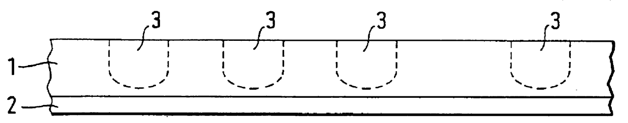
FIG. 1 illustrates a data carrying medium having a fluorescent layer 1 arranged on a substrate 2. In the fluorescent layer 1 there are provided in its surface or from its surface and towards the substrate 2 data carrying structures generally indicated by 3. It should be understood that viewed from the top of the medium the data carrying structures 3 will be able to be arranged in a linear or curved path, for example spirally as on a CD disc, or also in rows and columns, thus forming a matrix.

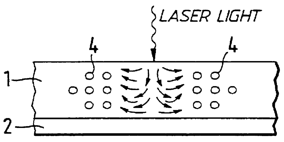
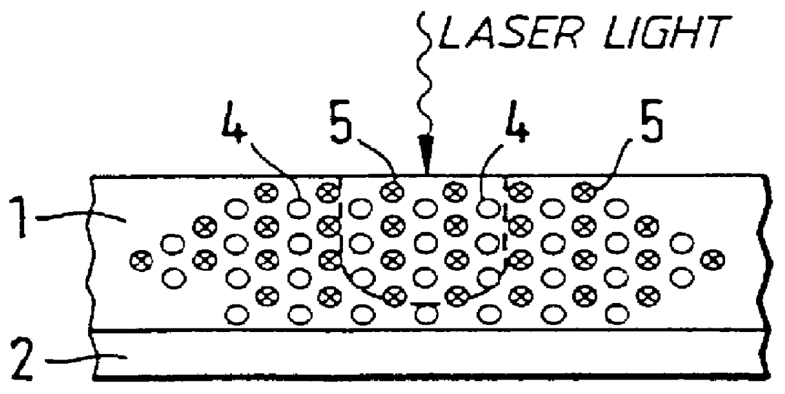
The fluorescent layer 1 comprises dye molecules 4 (FIG. 2) which are advantageously embedded in a transparent polymer base material, for example of modified polymethylmethacrylate (MPMMA). The dye molecules 4 may, for example, be rhodamine molecules. Each of the data carrying structures 3 has a specific degree of quenching for the fluorescence which is emitted from a data carrying structure when it is irradiated with fluorescence exciting radiation (FIG. 6). The degree of quenching for the fluor...


PUM

PropertyMeasurementUnit
diameteraaaaaaaaaa
thicknessaaaaaaaaaa
transparentaaaaaaaaaa

Abstract

PCT No. PCT / NO96 / 00125 Sec. 371 Date Nov. 20, 1997 Sec. 102(e) Date Nov. 20, 1997 PCT Filed May 22, 1996 PCT Pub. No. WO96 / 37888 PCT Pub. Date Nov. 28, 1996The optical storage device and method includes a fluorescent layer arranged on a substrate and having a surface. The fluorescent layer is composed of fluorescent dye molecules embedded in a transparent polymeric base material. A group of data-carrying structures are arranged in the fluorescent layer. Each of the data-carrying structures has more than two optical states represented by a specific degree of quenching of fluorescence emitted from the data-carrying structure when irradiated with a fluorescence exciting radiation.

Description

The invention concerns a data carrying method or medium, including a fluorescent layer arranged on a substrate, wherein data carrying structures are provided in the fluorescent layer in its surface or from its surface and towards the substrate.BACKGROUND OF INVENTIONDigital optical data storage media of the WORM type (Write Once, Read Many times) stores information written on a thin layer by means of a light pulse of high intensity, typically a strongly focused laser beam. Once data is written on to the layer, the layer cannot be returned to its original state, but it can be read many times by a weaker light beam which does not further influence the layer's physical state. Well known means in this context are thin metal film, flat glass or plastic surfaces or thin polymer film which contains a light-absorbing dye. In most cases such layers are provided between other layers, e.g. reflecting or protective layers. The layer stores information by undergoing a change under the influence ...

Claims


Application Information

Patent Timeline
Patent Type & Authority Patents(United States)
IPC IPC(8): G11B7/0045G11B7/013G11B7/005G11C13/04G11C11/56G11B7/244G11B7/00G11B7/24G11B7/004G11B7/24085
CPCG11B7/00451G11B7/00455G11B7/0052G11B7/24085G11B7/244G11C11/56G11C13/04G11B7/241
Inventor GUDESEN, HANS GUDENORDAL, PER-ERIK
Owner THIN FILM ELECTRONICS ASA
Why Eureka
Try Eureka