Consumption measurement system for remote reading

a technology of consumption measurement and reading, which is applied in the direction of transmission systems, alarms, antennas, etc., can solve the problems of linear antennas, no longer supportable to deduct energy and water costs, and high reading costs and time-consuming problems

Inactive Publication Date: 2000-09-05
FRAUNHOFER GESELLSCHAFT ZUR FOERDERUNG DER ANGEWANDTEN FORSCHUNG EV
View PDF12 Cites 56 Cited by
  • Summary
  • Abstract
  • Description
  • Claims
  • Application Information

AI Technical Summary

Problems solved by technology

In view of the rising cost of energy and water and also the very different consumption rates of individual tenants, e.g. singles as compared with families with children, it is no longer supportable to deduct the energy and water costs by a "rule of thumb" based on the rented domestic or business area.
In view of the great amount of time needed to enter every single flat of a block of flats or even every single room of a flat, reading is very expensive and time consuming.
The linear antennas used hitherto as transmitting / receiving antennas for this purpose, such as e.g. dipole antennas, vertical antennas or loop antennas, suffer, however, from the disadvantage that it is extremely difficult to meet the demands made on wireless consumption recording systems with the cited antenna types.
With this setup the antenna is accessible from outside and can be damaged very easily.
Furthermore, the wall mounting of such devices presents a fundamental problem because a vertical antenna thereby always finds itself close to the HF-disturbing wall of the house, which may be made of reinforced concrete e.g., or near to a metal radiator or gas meter.
The same is true for dipole antennas, since these cannot be mounted sufficiently far from the wall of the house or the radiator.
The mounting location also has the consequence that an omnidirectional radiation characteristic of the transmitting / receiving antenna does not necessarily make sense, since electrical energy is radiated unprofitably into the wall, which is fundamentally subject to losses.
The linear polarization of the electromagnetic field that the cited antennas radiate also has a disturbing effect since reflections of the electromagnetic radiation are accompanied by rotations of the plane of polarization of the radiation which lead to a reduced receiving power at the input of the receiver.

Method used


Image

  • Consumption measurement system for remote reading
  • Consumption measurement system for remote reading
  • Consumption measurement system for remote reading

Examples


Embodiment Construction

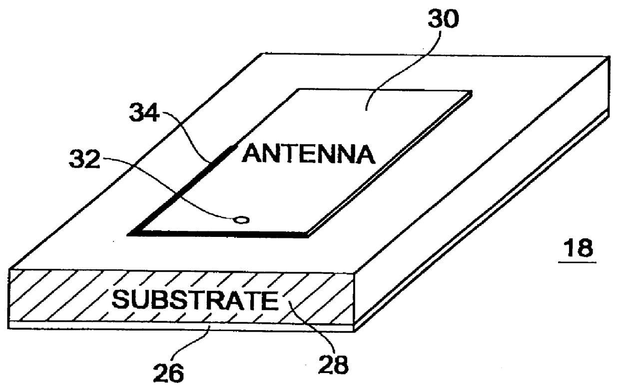
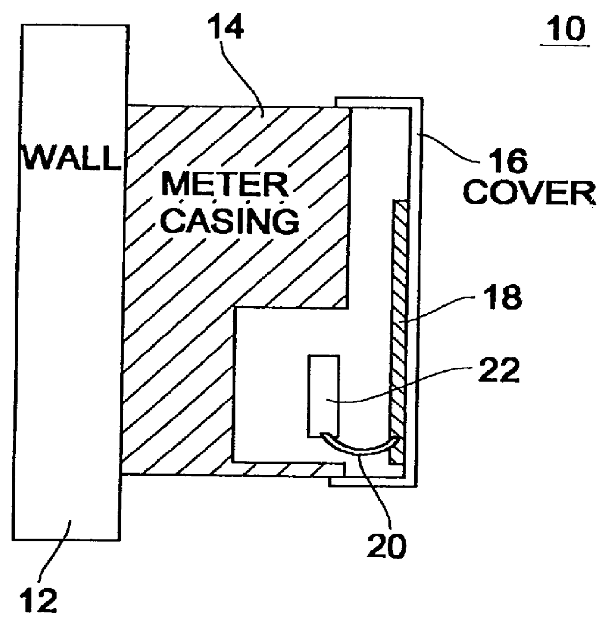
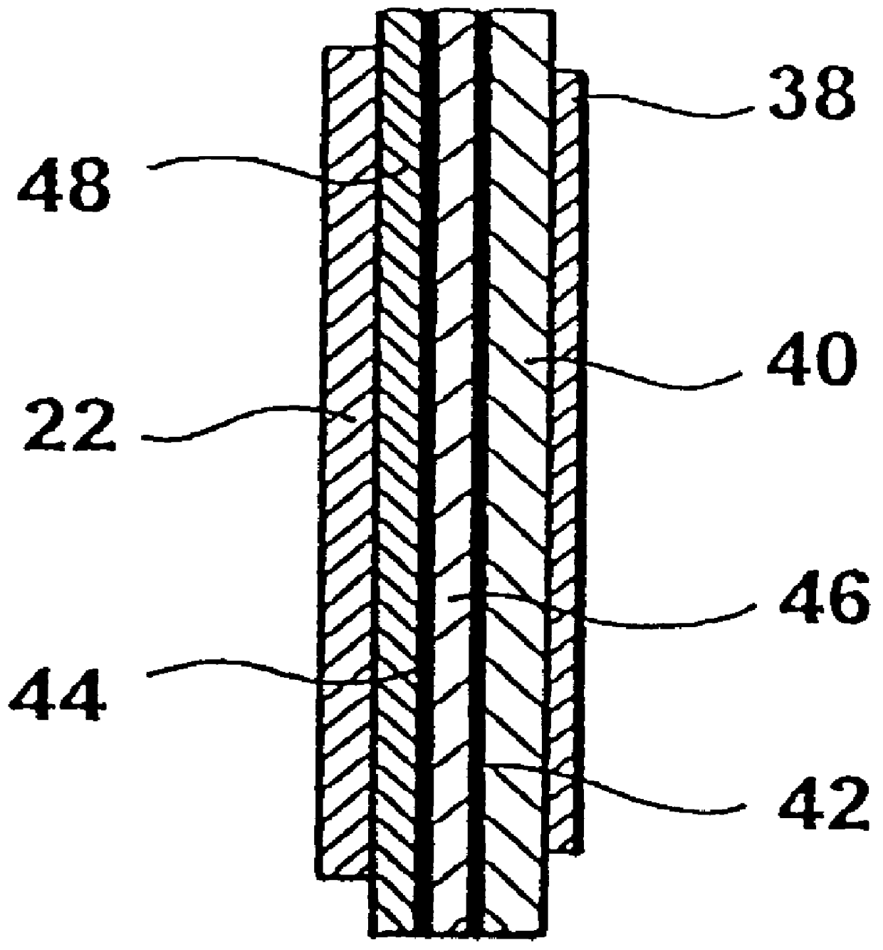
FIG. 1 shows a consumption recording system 10 affixed to a wall 12. An embodiment of the present invention will be described in terms of a gas meter. It is, however, clear that the consumption recording system according to the present invention can equally well be a water meter, a heating meter and similar. A metallic gas meter casing 14 is terminated by a plastic casing cover 16 on the side opposite the wall 12. The casing cover 16 is normally provided with a lead seal to prevent unauthorized manipulations of the gas meter. A planar antenna 18 is affixed to the casing cover 16 with glue or other suitable holding devices. The planar antenna 18 is fed from a radio module 22 via a coaxial line 20. The radio module is in contact with a gas meter device (not shown) so as to process suitably the recorded gas meter reading and to convert it into data signals which can be transmitted via the planar antenna 18. The gas meter device is contained in the gas meter casing 14. It is obvious to ...


PUM


Abstract

PCT No. PCT/EP96/04068 Sec. 371 Date Mar. 20, 1998 Sec. 102(e) Date Mar. 20, 1998 PCT Filed Sep. 17, 1996 PCT Pub. No. WO97/11445 PCT Pub. Date Mar. 27, 1997A consumption recording system affixed to a wall comprises a consumption recording device and a radio module, which is connected to the consumption recording device. A microstrip antenna is connected to the radio module. The microstrip antenna is placed within a non-metallic casing cover of the consumption recording device in such a way that the main radiation direction of the microstrip antenna is directed perpendicularly away from the wall.

Description

1. Field of the InventionThe present invention relates to consumption recording systems with remote reading and in particular to consumption recording systems in which planar antennas are used to radiate a signal corresponding to a measured consumption.2. Description of Prior ArtIn blocks of flats or office blocks with a central energy and water supply, it is necessary to record the individual consumption of each and every tenant as regards gas, heating and / or water, as separate items, and to charge accordingly. In view of the rising cost of energy and water and also the very different consumption rates of individual tenants, e.g. singles as compared with families with children, it is no longer supportable to deduct the energy and water costs by a "rule of thumb" based on the rented domestic or business area.This has led to the provision of a separate meter for electrical energy for each tenant or proprietor, all the meters then being normally located in a common room, e.g. in the c...

Claims


Application Information

Patent Timeline
Patent Type & Authority Patents(United States)
IPC IPC(8): G08C17/02G08C17/00H01Q9/04H01Q1/22
CPCG08C17/02H01Q1/22H01Q1/2233H01Q9/0421
Inventor PERTHOLD, RAINERGERHAUSER, HEINZ
Owner FRAUNHOFER GESELLSCHAFT ZUR FOERDERUNG DER ANGEWANDTEN FORSCHUNG EV
Why Eureka
Try Eureka