Micromotors, linear motors, micropumps, methods of using the same, microactuators, methods of controlling flow properties of fluids, and apparatuses for controlling flow properties of fluids

a technology of fluid flow properties and micropumps, which is applied in the direction of generators/motors, water supply installations, transportation and packaging, etc., can solve the problems of heterogeneous fluids with poor dispersion stability, variable properties of fluids, and high cost of liquid crystal compounds, so as to reduce friction and reduce friction

Inactive Publication Date: 2000-09-12
NEW TECH MANAGEMENT INC
View PDF7 Cites 48 Cited by
  • Summary
  • Abstract
  • Description
  • Claims
  • Application Information

AI Technical Summary

Benefits of technology

The fluid container 211 is constituted of a cylindrical body to form a side wall of the housing 210 and the bottom 213. The bottom 213 functions to close the cylindrical body, and the central portion of the bottom 213 protrudes upward. The upper end of the protruded bottom is provided with a lower bearing section 214a. By the lower bearing section 214a, a lower part of the rotating shaft 220 (lower rotating shaft 222) is rotatably borne. The lower bearing section 214a is provided with a rotational contact point means 246 which is filled with mercury 247 as a conductive material. The rotational contact point means 246 is in contact with the lower rotating shaft 222. From the rotational contact point means 246, a conductor 248 for supplying power from the outside power supply is extended. The lower bearing section 214a is provided with a bearing means 216 to reduce friction between the rotating shaft 220 and the lower bearing section 214a.
The top of the fluid container 211 is made open, and the lid 212 is engaged with the open top to close the housing 210. The center of the lid 212 is provided with an upper bearing section 215. By the upper bearing section 215, an upper part of the rotating shaft 220 (upper rotating shaft 221) is rotatably borne. The upper bearing section 215 is provided with a rotational contact point means 245 which is filled with mercury 247 as a conductive material. From the rotational contact point means 245, a conductor 248 for supplying power from the outside power supply is extended. The upper bearing section 215 is provided with a bearing means 216 to reduce friction between the rotating shaft 220 and the upper bearing section 215.

Problems solved by technology

There are, however, problems in the fluids whose properties are varied upon application of a voltage.
For example, the liquid crystal compounds are very expensive, or the heterogeneous fluids show poor dispersion stability.
The heterogeneous ER fluids, however, have a problem in that sedimentation or flotation of particles takes place because of a difference in specific gravity between the particles and the medium.
Even if the particles and the medium have the same specific gravity, the same problem of sedimentation or flotation of particles takes place with time because the temperature dependence of the specific gravity of the particles and that of the specific gravity of the medium are different from each other at low or high temperatures.
For this reason, linear control of the heterogeneous ER fluids is difficult, and in many cases, complicated control means such as feedback control is necessary.
However, the homogeneous ER fluids such as liquid crystals are very expensive, so that they are not broadly employed for an industrial use, liquid crystals are only used for, for example, display devices of extremely high value added.
Though the estimated temperature range wherein the ER fluids are used is from about -30.degree. C. to about 120.degree. C., the liquid crystals cannot be driven in such a wide temperature range.
As described above, the homogeneous ER fluids are advantageous as the ER fluids from the control viewpoint, but they are very expensive and their working temperature range is narrow.
On the other hand, the heterogeneous ER fluids are relatively inexpensive, but they are difficult to control and have a problem of fluid stability such as occurrence of particle sedimentation or particle flotation.
Moreover, there is no report about production of a jet flow.

Method used


Image

  • Micromotors, linear motors, micropumps, methods of using the same, microactuators, methods of controlling flow properties of fluids, and apparatuses for controlling flow properties of fluids
  • Micromotors, linear motors, micropumps, methods of using the same, microactuators, methods of controlling flow properties of fluids, and apparatuses for controlling flow properties of fluids
  • Micromotors, linear motors, micropumps, methods of using the same, microactuators, methods of controlling flow properties of fluids, and apparatuses for controlling flow properties of fluids

Examples


example 1

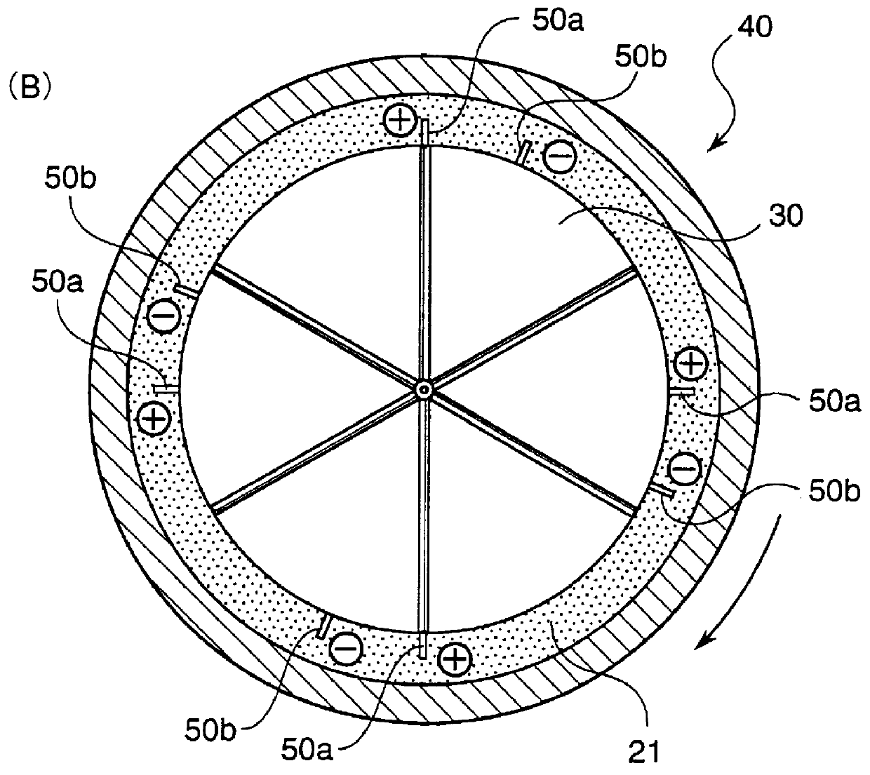
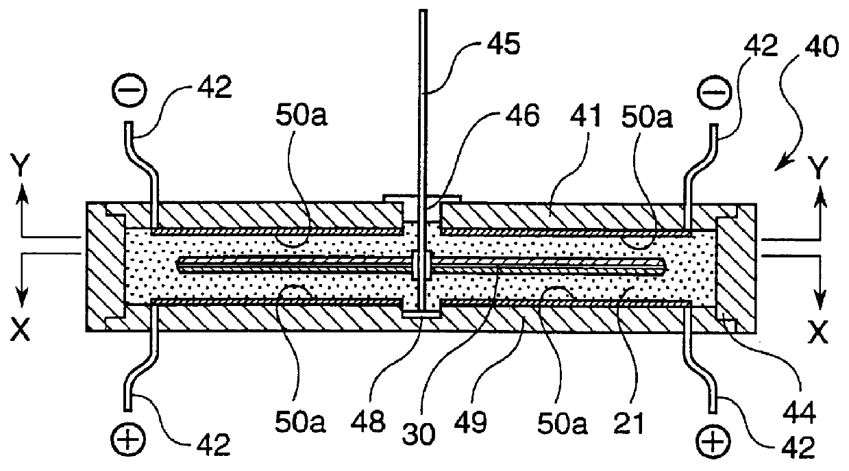
A SE type ECF motor having a structure shown in FIG. 2(A) was fabricated. That is, as a fluid container of the SE type ECF motor, a cylinder having an inner diameter of 16 mm and a depth of 3.5 mm was used. The bottom surface of the cylinder and the lower surface of a lid each was provided with four pairs of electrodes in such a manner that the angle between a pair of electrodes (positive electrode and negative electrode) was 22.5.degree. and the angle between the adjacent positive electrodes was 90.degree..

A circular film having a rotating shaft at its center and having a diameter of 15 mm was used as a rotator. As the flow receiving members, 8 convex bars each having a section of right-angled triangle were attached to the upper surface of the circular film, and 8 convex bars having the same section as above were attached to the lower surface of the circular film (total number of bars: 16).

The fluid container was filled with 16 ml of dibutyl decanedioate (DBD).

Then, a direct-curren...

example 2

The SE type ECF motor was driven in the same manner as in Example 1, except that the rotator having a flow receiving member consisting of 16 convex bars was replaced with a rotator having a flow receiving member consisting of 8 convex bars (4 convex bars each having a section of right-angled triangle attached to the upper surface and 4 convex bars having the same section attached on the lower surface). As a result, the SE type ECF motor underwent steady rotation at 340 rpm, and the rotational direction was the same as in Example 1.

example 3

The SE type ECF motor was driven in the same manner as in Example 1, except that linalyl acetate was used in place of the dibutyl decanedioate (DBD). As a result, the SE type ECF motor underwent steady rotation at 740 rpm, the intensity of the current was 1.8 .mu.A, and the rotational direction was the same as the flow direction of the linalyl acetate (i.e., direction of the positive electrode to the negative electrode).


PUM


Abstract

The present invention provides a use of an electro-sensitive movable fluid, that is, a micromotor, a linear motor, a micropump and a method of using the micropump, a microactuator, and an apparatus which these devices are applied to, and a method and an apparatus of controlling flow properties of a fluid.

Description

The present invention relates to micromotors using electro-sensitive movable fluids (electro-conjugate fluid, ECF) which move between electrodes upon application of a voltage, and more particularly to extremely thin micromotors using the electro-sensitive movable fluids. The invention also relates to linear motors using the electro-sensitive movable fluids. The invention further relates to micropumps using the electro-sensitive movable fluids, methods of using the micropumps and microactuators using the micropumps as cooling means. The present invention furthermore relates to methods of controlling flow properties of substantially dielectric fluids by applying a voltage and apparatuses for controlling flow properties of fluids.It is known that the characteristics of certain kinds of dielectric fluids vary when the dielectric fluids are subjected to electric fields. In case of liquid crystals, for example, when a voltage is applied to liquid crystal compounds, orientation properties ...

Claims


Application Information

Patent Timeline
Patent Type & Authority Patents(United States)
IPC IPC(8): F15B21/00F15C5/00F15C1/00F15B21/06F15C1/04H02N11/00F16K99/00H01J41/18
CPCF15B21/065F15C1/04F15C5/00F16K99/0001F16K99/0007F16K99/0013F16K99/0042F16K99/0057H01J41/18H02N11/006F16K2099/0094Y10S137/909Y10T137/0318Y10T137/2082Y10T137/2191Y10T137/85978
Inventor YOKOTA, SHINICHIOTSUBO, YASUFUMINAKADA, TAKESHIEDAMURA, KAZUYA
Owner NEW TECH MANAGEMENT INC
Why Eureka
Try Eureka