Internally insulated, corrosion resistant pipeline

a technology of corrosion resistance and internal insulation, applied in the direction of flexible pipes, pipes, pipe protection, etc., can solve the problems of hydrate formation and wax deposition, limited pressure carrying ability of conventional external insulation, and serious problems such as the effect of affecting the corrosion resistance of the internal insulation

Inactive Publication Date: 2000-09-12
J RAY MCCDERMOTT SA
View PDF7 Cites 106 Cited by
  • Summary
  • Abstract
  • Description
  • Claims
  • Application Information

AI Technical Summary

Problems solved by technology

When the flow line contents cool to sufficiently low temperatures, two serious problems can occur, hydrate formation and wax deposition.
Conventional external insulation is limited by pressure carrying ability and water absorption at deeper water depths.
The resulting product is highly effective but costly to manufacture and install.
These methods are costly as well.
Another proble

Method used


Image

  • Internally insulated, corrosion resistant pipeline
  • Internally insulated, corrosion resistant pipeline
  • Internally insulated, corrosion resistant pipeline

Examples


Embodiment Construction

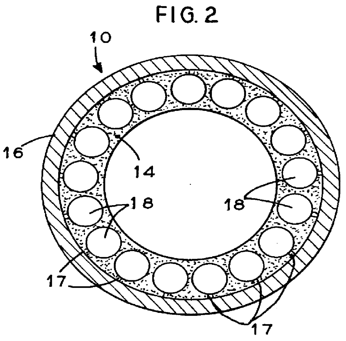
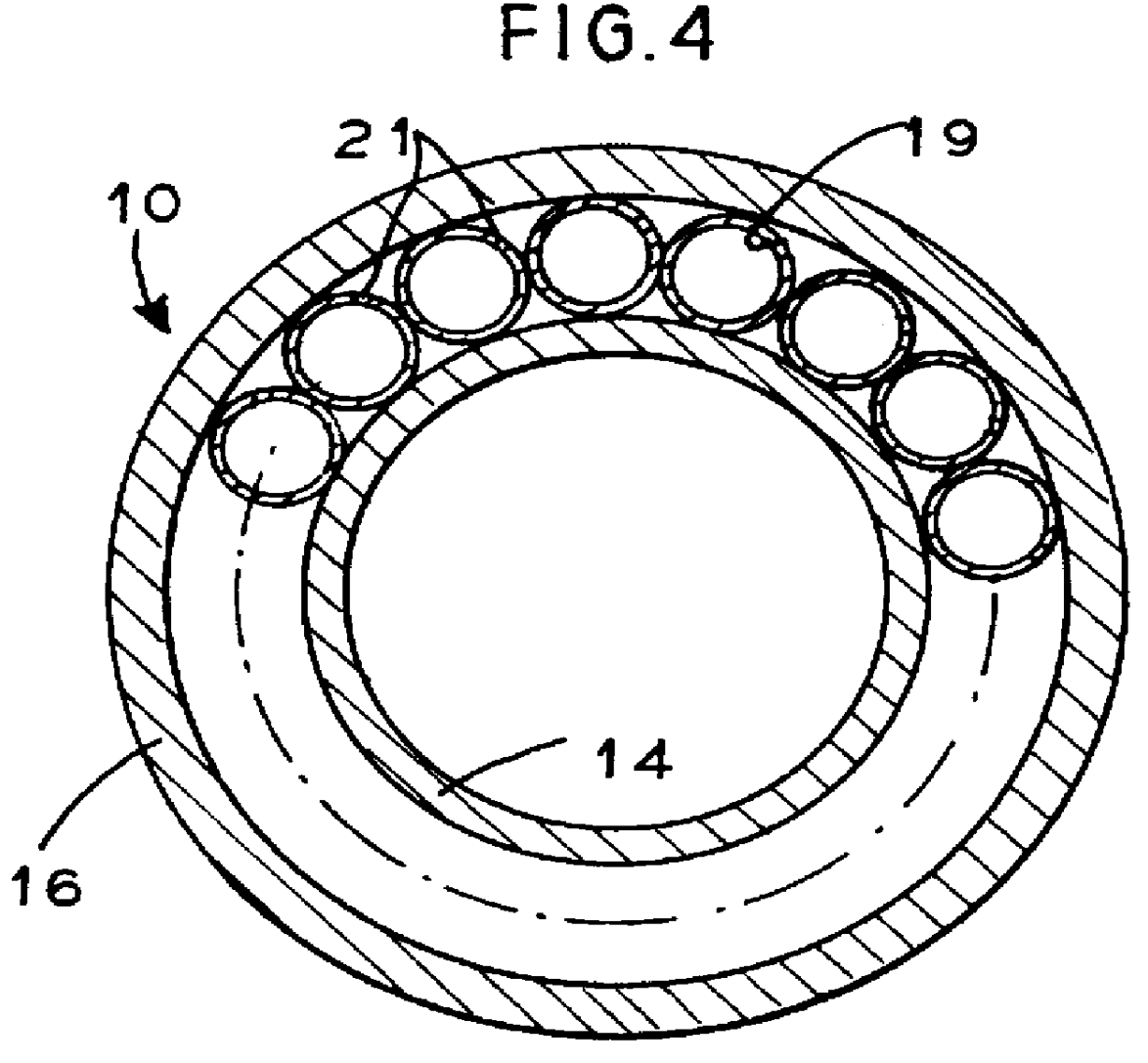
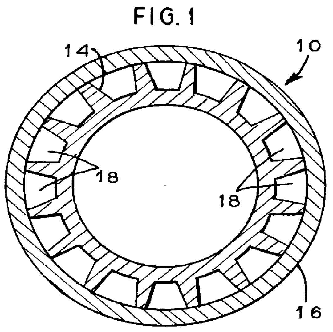
Referring to the drawings, it is seen in FIG. 1 that the invention is generally indicated by the numeral 10. Pipeline 10 is generally comprised of a liner 14 and an outer pipe 16.

The liner 14 is preferably a polymeric material to act as the carrier for the produced hydrocarbon or corrosive / erosive fluid. The liner (carrier) pipe can be formed of any polymer material such as high-density polyethylene (HDPE), Carilon.RTM., polyamide 11 (PA11), or a composite of multiple materials.

In the preferred embodiment, the liner 14 is provided with a plurality passages 18 around the outer perimeter of the liner. The passages 18 may be longitudinal or helical.

FIG. 1 illustrates passages 18 that are essentially U-shaped in cross section. FIG. 2 is an alternate embodiment and illustrates passages 18 that are circular in cross section. Each passage 18 is provided with a vent hole 17 to allow passage of gas build-up in the inter-annular region to pass through the passages 18. FIG. 3 is an alternate e...


PUM


Abstract

An internally insulated, corrosion resistant pipeline. An inner fluid barrier is formed preferably by a polymer liner. The outer pipe may be a steel pipe. The liner is provided with a plurality of passages or an open annulus. The passages in the liner or annulus between the pipe and liner are filled with an insulation material.

Description

BACKGROUND OF THE INVENTION1. Field of the InventionThe invention is generally related to pipelines and more particularly to an internally insulated, corrosion resistant configuration.2. General BackgroundIn the offshore production of oil and gas, subsea flowlines transport fluids produced from the offshore gas and / or oil wells to a production station located some distance from the well. The contents of a flowline typically include oil, natural gas, and water. Subsea pipelines transport a single fluid such as oil, gas, or water for the purposes of export or injection. The mixture is at a warm temperature when first leaving the reservoir, but the contents cool as they flow through the line, with the cooling rate being rapid when the production flow is stopped (shut-in). When the flow line contents cool to sufficiently low temperatures, two serious problems can occur, hydrate formation and wax deposition. Hydrates form at sufficiently low temperatures when natural gas and water combin...

Claims


Application Information

Patent Timeline
IPC IPC(8): F16L59/00F16L59/14
CPCF16L59/143
Inventor OHRN, THEODORE ROBERTTAYLOR, JR., LELAND HARRIS
Owner J RAY MCCDERMOTT SA
Why Eureka
Try Eureka