Infrared radiation sensitive device

a sensitive device and infrared radiation technology, applied in the direction of heat measurement, optical radiation measurement, instruments, etc., can solve the problems of reducing the performance of the device, difficult handling of the infrared sensor device, and pyroelectric infrared sensor device in the prior art, so as to improve the relative detection rate and reduce the cost. , the effect of reducing the cost of mass production

Inactive Publication Date: 2000-09-19
MURATA MFG CO LTD
View PDF7 Cites 9 Cited by
  • Summary
  • Abstract
  • Description
  • Claims
  • Application Information

AI Technical Summary

Benefits of technology

to provide a pyroelectric infrared sensor device having an improved relative detection rate and wherein the relative detection rate can be varied simply, while at the same time rendering mass production thereof easier and cheaper.

Problems solved by technology

Unfortunately, the aforesaid prior art pyroelectric infrared sensor devices encounter several difficulties, which follow.
Since it has been strictly required to obtain thermal insulation while decreasing the thickness of the pyroelectric body, the mechanical strength of such pyroelectric body itself might be weakened so as to reduce its durability against application of thermal shocks, thereby making the handling of such pyroelectric infrared sensor devices difficult.
In other words, if the pyroelectric body is decreased in thickness, then certain risks might arise: mechanical damage including micro-cracks can occur in the pyroelectric infrared sensor devices per se due to significant thermal variations upon application of external vibrations and shocks as well as upon irradiation of strong infrared light rays thereon, while the performance thereof can decrease due to degradation of heat flow balance.
Furthermore, since the pyroelectric body per se becomes brittle, making it difficult for the pyroelectric body to be reliably supported by adhesion on a substrate, which in turn makes it very difficult both to settle its support method and to attain accurate position alignment accuracy.
Due to the above difficulties the resulting performance can decrease undesirably.
Another problem faced by the prior art is that since in most cases the thickness of the pyroelectric body itself is designed to fall within the range of from 70 to 100 micrometers, the production yield remains low, rendering it extremely difficult to manufacture or fabricate the pyroelectric infrared sensor devices per se.
This results in the manufacturing costs of the prior art pyroelectric infrared sensor devices being undesirably increased.
More specifically, in the prior art pyroelectric infrared sensor device 5, it should be required in order to change the relative detectivity, the light receiving area of the pyroelectric body 6 for receiving infrared light rays must be changed, which results in increasing complexity and time.
For this reason, the prior art device is not adaptable for use in stable mass production while at the same time it is rendered difficult to manufacture the same at low cost.

Method used


Image

  • Infrared radiation sensitive device
  • Infrared radiation sensitive device
  • Infrared radiation sensitive device

Examples


Embodiment Construction

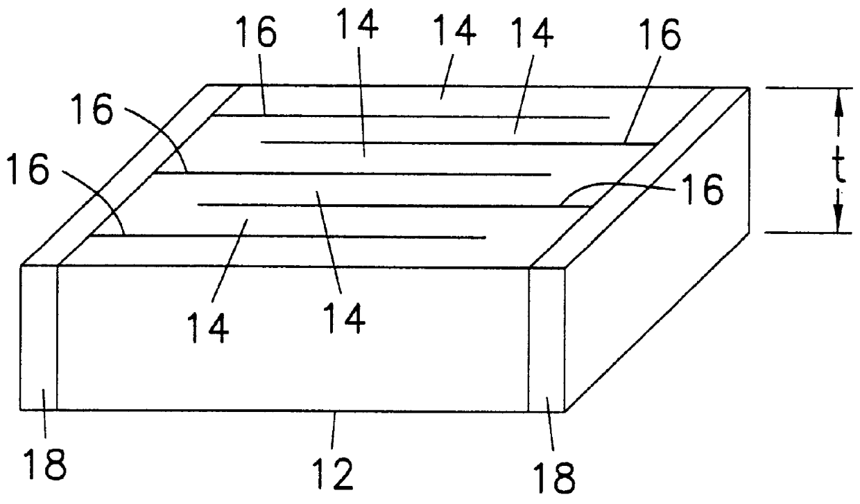
Referring now to FIG. 1, a pyroelectric infrared sensor device 10 includes a pyroelectric unit 12 which is of the planar rectangular shape and has a predefined thickness t. The pyroelectric unit 12 contains a plurality of pyroelectric layers 14, wherein rectangular plate-like internal electrodes 16 are formed between the pyroelectric layers 14, by way of example. In other words, the internal electrodes 16 are disposed within the pyroelectric unit 12 in such a manner that these are spaced apart at specified distances in the width direction thereof.

A first group of internal electrodes 16 extends from a first end of the pyroelectric unit 12 toward a second end thereof along the length direction thereof. A second group of internal electrodes 16 extends from the second end to the first end in such a way that the former and the latter are alternately formed. These internal electrodes 16 are formed such that respective terminal edges thereof are exposed alternately at the first end surface...


PUM

PropertyMeasurementUnit
thicknessaaaaaaaaaa
thicknessaaaaaaaaaa
temperaturesaaaaaaaaaa

Abstract

A pyroelectric infrared sensor device (10) with improved relative detectivity and with which it is easier to change the relative detectivity, and also with reduced manufacturing cost. This sensor device (10) includes a pyroelectric unit (12) having an alternating lamination of internal electrodes (16) and pyroelectric layers (14) with a predetermined thickness t. The ends of the internal electrodes (16) which extend perpendicular to the length direction thereof are respectively exposed at alternate terminal surfaces of the pyroelectric unit (12) and external electrodes (18) are connected to the terminal ends of those internal electrodes (16), respectively. The pyroelectric infrared sensor device (10) is horizontally polarized between the internal electrodes (16) via the external electrodes (18) with respect to the infrared light receiving plane thereof. The ends of the internal electrodes (16) perpendicular to the width direction thereof are exposed at the top and bottom surfaces of the pyroelectric unit (12) in such a manner that its top surface side will act as the light receiving plane of the pyroelectric infrared sensor device (10).

Description

1. Field of the InventionThe present invention relates to an infrared radiation sensitive device, and more particularly to an infrared radiation sensitive device comprising a pyroelectric unit, a light receiving face on said pyroelectric unit for receiving infrared light radiated from an object to be detected, and a pair of external electrodes on opposite end surfaces of said pyroelectric unit respectively.2. Description of the Prior ArtOne prior known pyroelectric infrared sensor device 1A is shown in FIG. 7A. This prior art device includes a rectangular-plate-shaped pyroelectric body 1a having top and bottom surfaces on which electrodes 2a, 3a are formed respectively with polarization treatment being applied between the electrodes 2a, 3a in the direction designated by the arrows shown in FIG. 7A. Another prior art pyroelectric infrared sensor device 1B is shown in FIG. 7B which includes a pyroelectric body 1b having side surfaces on both of which electrodes 2b, 3b are formed with ...

Claims


Application Information

Patent Timeline
Patent Type & Authority Patents(United States)
IPC IPC(8): G01J5/34G01J5/10H01L37/00H01L37/02G01K7/00G01J1/02H01L31/0264
CPCG01J5/34H01L37/02H01L2224/48091H01L2924/00014H10N15/10
Inventor ITO, SATORU
Owner MURATA MFG CO LTD
Why Eureka
Try Eureka