Non-volatile MEMS micro-relays using magnetic actuators

a magnetic actuator and micro-relay technology, applied in relays, generators/motors, electrostatic generators/motors, etc., can solve the problems of preventing high-density integration of relays, affecting the operation of relays, and requiring undesirable dissipation of power

Inactive Publication Date: 2000-09-26
WSOU INVESTMENTS LLC +1
View PDF6 Cites 176 Cited by
  • Summary
  • Abstract
  • Description
  • Claims
  • Application Information

AI Technical Summary

Problems solved by technology

Although such an actuation mechanism can deliver large actuation forces, the current required to maintain the switch in the on-state requires undesirable dissipation of a large amount of power (e.g. hundreds of milliwatts) in the control circuit of the relay.
Such high power dissipation limits the integration of MEMS relays into CMOS circuitry where the amount of power thus dissipated results in an operation bottleneck, and also prevents high-density integration of such relays.
In MEMS-based relays, in particular, power dissipation is an important issue since the power handling capability of the substrates is limited.
Similarly, prior art magnetic actuators utilizing magnetic fields from a current sourc

Method used


Image

  • Non-volatile MEMS micro-relays using magnetic actuators
  • Non-volatile MEMS micro-relays using magnetic actuators
  • Non-volatile MEMS micro-relays using magnetic actuators

Examples


Embodiment Construction

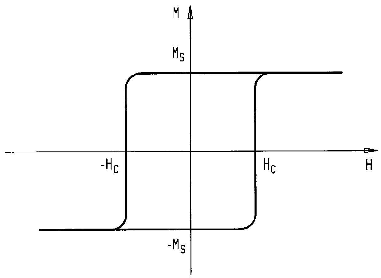
The actuation mechanism according to the present invention provides suitable means to achieve both attractive and repulsive forces in a MEMS device while substantially eliminating the need for power dissipation to maintain the switched state. The direction of actuation force (i.e. attractive vs. repulsive) can be easily reversed by changing the direction of current flow through a set of control conductors. In principle, the control current need only to be supplied over a time duration in which the direction of magnetization (i.e. polarization) of the magnetic material is being reversed and latched, and the need for power dissipation is therefore eliminated when the actuation status is simply being maintained. Some exemplary applications for such mechanical actuation with low to no power dissipation include, without limitation, mechanical relays and reflecting light switches.

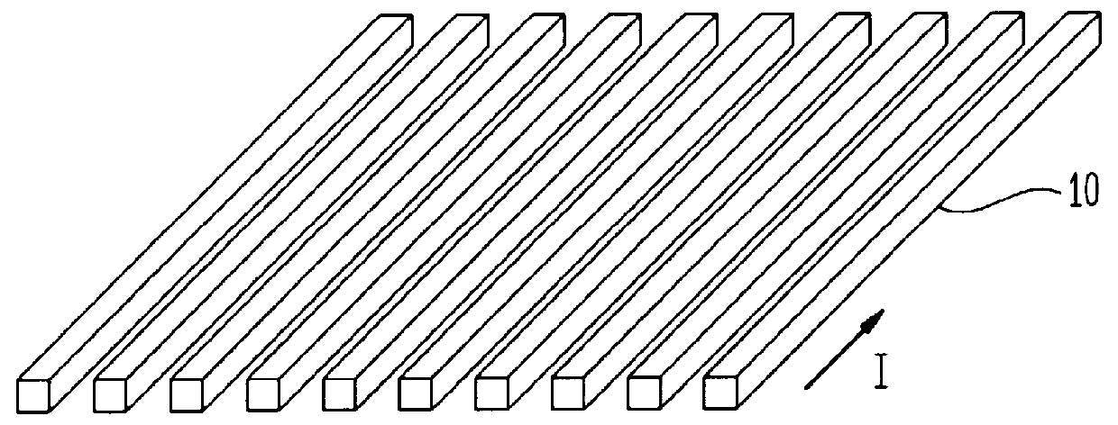
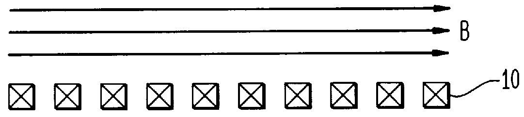
While an electrically-generated magnetic field is usually produced by using solenoid windings, such a solenoid...


PUM


Abstract

An actuation device employing square-loop latchable magnetic material having a magnetization direction (polarization) capable of being changed in response to exposure to an external magnetic field is disclosed. The magnetic field is created by a conductor assembly with non-solenoid configuration. Once the magnetization direction of the material is so changed, the external magnetic field is no longer required to maintain the new magnetization direction. The latchable magnetic material is disposed on the mobile electrode of a switching device, and another magnetic material is disposed in spaced relation to the latchable magnetic material on a stationary electrode or surface. By applying an electrical current to a conductor assembly arranged proximate the latchable material, a magnetic field is created about the latchable magnetic material, to change the magnetization direction and thereby enable the attraction or repulsion of another magnetic material located on the stationary electrode. The resulting relative displacement of the mobile and stationary electrodes effects the selective connection or disconnection of electrical contacts carried on or associated with the respective electrodes of the actuation device without requiring additional power in order to maintain the switched state of the electrodes.

Description

1. Field of the InventionThe present invention relates to Micro Electro-Mechanical Systems (MEMS), and more particularly to the magnetic actuation of a MEMS micro-relay using latchable magnetic materials.2. Description of the Related ArtMagnetic forces can be used to induce mechanical motion ("actuation") of magnetic materials. Electric current flowing through a conductor (e.g. a wire) induces a magnetic field around the conductor due to Faraday's law of induction (e.g. an electromagnet), and this mechanism is used to induce mechanical motion in many applications. Some implementation examples of electromagnetic actuation includes mechanical relays, bells used for fire alarm systems, and magnetic levitation trains.Mechanical relays generally consist of a mobile mechanical electrode that is pulled into contact with a stationary electrode via magnetic force. In the most general implementation, a magnetic material is attached to the mobile electrode, and an electromagnet is positioned o...

Claims


Application Information

Patent Timeline
IPC IPC(8): H01H50/00H02K57/00H01H51/22B81B3/00H01H50/42H01H51/27
CPCH01H50/005H02K57/006H01H2050/007Y10S310/06H02K99/20
Inventor BISHOP, DAVID JOHNJIN, SUNGHOKIM, JUNGSANGRAMIREZ, AINISSA G.
Owner WSOU INVESTMENTS LLC
Why Eureka
Try Eureka