Operation microscope

Inactive Publication Date: 2000-10-03
KK TOPCON
View PDF6 Cites 4 Cited by
  • Summary
  • Abstract
  • Description
  • Claims
  • Application Information

AI Technical Summary

Benefits of technology

The present invention has been made in view of the above circumstance, and therefore it is an object of the present invention to provide an operation microscope for clear

Problems solved by technology

Thus, it is a disadvantage that the virtual image A of the illumination light source would obstruct the observation when the observer observes the inherent image Ea of the eye to be examined.
Accordingly, the virtual image is too bright in comparison with other portions, and then it is difficult to observe the other portions by the observer.
Also, blurs or the like caused by diffused reflection produce in the vicinity of the virtual image of the illumination light source.
Further, since the virtual image of the illumination light source is extremely bright, the virtual image offsets the observation light from a portion deeper from the eye to be examined than the portion where the virtual image is positioned, so that it is difficult to observe the deep portion.
Also, the attention of the observer would be alwa

Method used


Image

  • Operation microscope
  • Operation microscope
  • Operation microscope

Examples


Embodiment Construction

An embodiment of the present invention will now be described with reference to the accompanying drawings.

[Principle of the Invention]

The principle of the present invention will be first described on the basis of FIGS. 2 and 3.

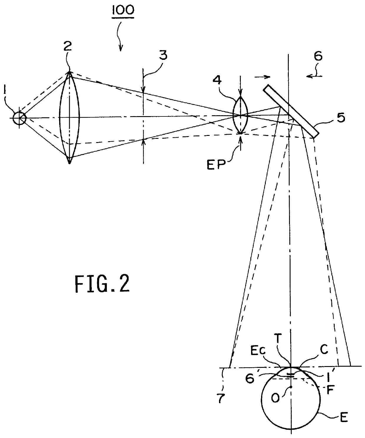
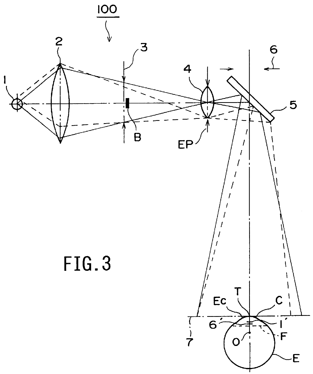
FIG. 2 shows the structure of the conventional operation microscope and FIG. 3 shows the structure of an operation microscope according to the embodiment of the present invention.

As shown in FIG. 2, the conventional operation microscope has an illumination optical system 100 for illuminating an eye E to be examined. Incidentally, since the observation optical system is not directly related to the present invention, only an entrance pupil 6 of the observation optical system (hereinafter simply referred to as an entrance pupil 6) is shown.

As shown in FIG. 2, the illumination optical system 100 has a light source 1, a condenser lens 2, an illumination field stop 3, a relay lens 4, and a half-mirror 5.

The illumination light emitted from the light source 1 is conver...


PUM


Abstract

A light-shielding member is provided at an optically conjugative position with an optical system composed of optical components (including a corneal convex mirror) interposed between an entrance pupil and the light-shielding member on an optical path of an illumination optical system in order to prevent a virtual image of a light source from being observed in an observation optical system. The position where the light-shielding member is located is the vicinity of an illumination field stop and closer to the eye to be examined than the illumination field stop. A size of the light-shielding member is theoretically determined by a product of a diameter of the entrance pupil of the observation optical system, and an observation magnification of the optical system composed of the corneal convex mirror and a relay lens.

Description

BACKGROUND OF THE INVENTION1. Field of the InventionThe present invention relates to an operation microscope for illuminating and observing eyes to be examined, of a subject such as a patient in diagnosis, medical treatment and operation in ophthalmology.2. Description of Related ArtAn operation microscope is known which illuminates eyes of a subject such as a patient with an illumination optical system and with which an observer can stereoscopically observe the illuminated eyes through a binocular stereoscopic observation optical system in diagnosis, medical treatment and operation in ophthalmology.However, in the case where an eye is illuminated with a conventional operation microscope, a cornea of the eye to be examined acts as a convex reflective mirror, so that a virtual image of the illumination light source is formed on the focal surface of the cornea. For this reason, as shown in FIG. 1, the virtual image A of the illumination optical source of the illumination optical syste...

Claims


Application Information

Patent Timeline
IPC IPC(8): A61B3/13G02B21/06A61B19/00
CPCA61B3/156
Inventor AKIYAMA, HIROSHI
Owner KK TOPCON
Why Eureka
Try Eureka