Scanning tunnel microscope

a tunnel microscope and scanning tunnel technology, applied in the direction of mechanical measurement arrangements, mechanical roughness/irregularity measurements, instruments, etc., can solve the problems of unclear observation portion and inconvenient stm

Inactive Publication Date: 2000-10-03
OLYMPUS OPTICAL CO LTD
View PDF13 Cites 54 Cited by
  • Summary
  • Abstract
  • Description
  • Claims
  • Application Information

AI Technical Summary

Problems solved by technology

Although a conventional STM can obtain a surface image having a very high resolution in the real space, an observation portion is unclear or the STM is not suitable for observation for a specific portion within a narrow range because the observation portion on the sample surface is observed with eyes and the above observation operation is performed.

Method used


Image

  • Scanning tunnel microscope
  • Scanning tunnel microscope
  • Scanning tunnel microscope

Examples


first embodiment

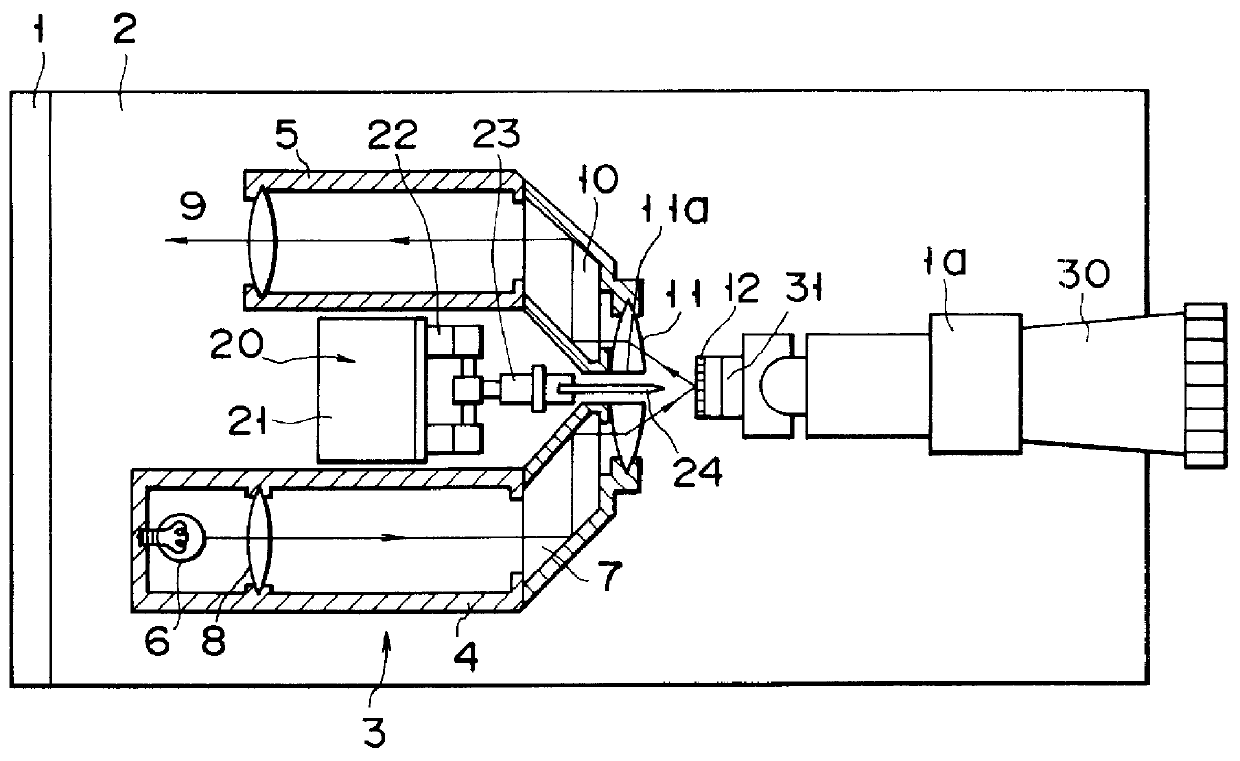
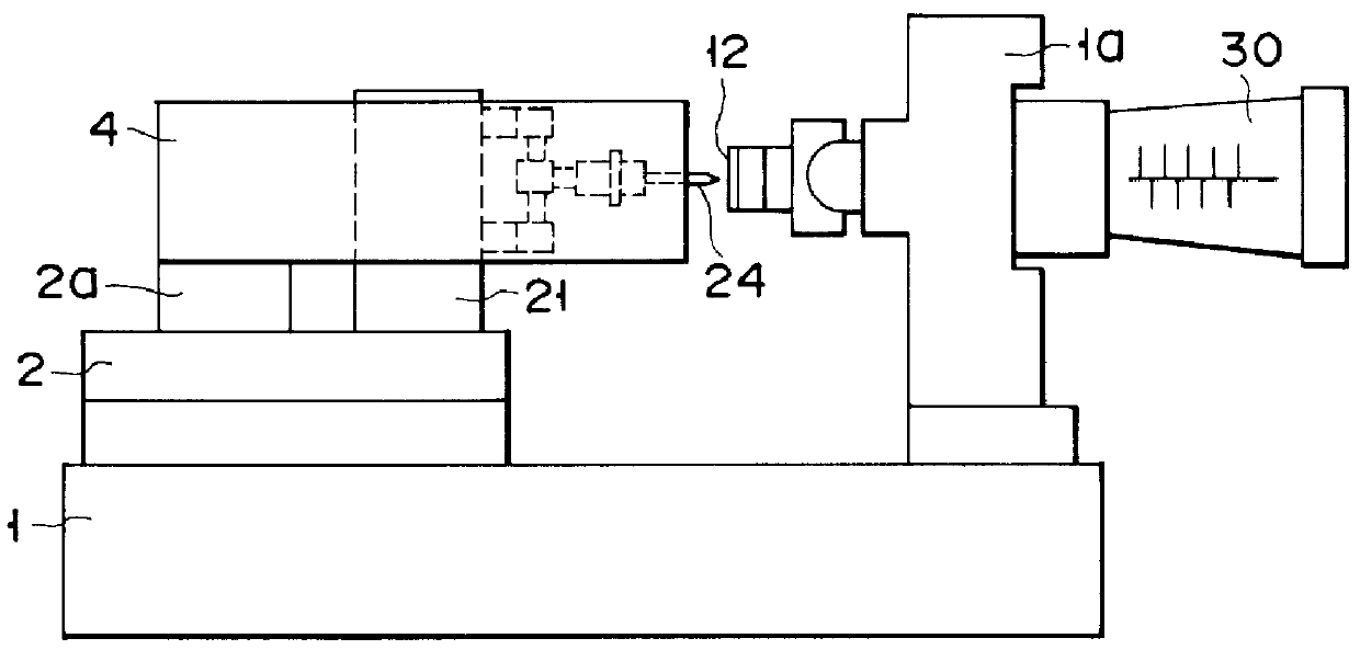
In FIGS. 1 and 2 which show the first embodiment, reference numeral 1 denotes a base. A movable stage 2 is mounted on the base 1 so as to be movable in the z direction. An STM field observation optical system (optical microscope) 3 is fixed on the movable stage 2 by a column 2a. This system 3 has a cylindrical light source housing 4 and a cylindrical observation housing 5 in tandem with the housing 4. A light source 6, a first prism 7, and a focusing lens 8 are arranged at one end, near the other end, and at a middle portion in the light source housing 4, respectively. A focusing lens 9 and a second prism 10 are arranged at one end and near the other end in the observation housing 5, respectively. A common convergent lens 11 (objective lens) is mounted at the other-end portions of the housings 4 and 5. A through hole 11a is formed at the center of the convergent lens 11.

In the STM field observation optical system having the above arrangement, light emitted from the light source 6 is...

second embodiment

A scanning tunnel microscope according to the present invention will be described with reference to FIGS. 6 and 7.

In this embodiment, a mechanism for holding a sample 12 and a coarse movement driving mechanism for an STM field observation optical system 3 and a probe 24 are the same as those of the above embodiment, and a detailed description thereof will be omitted.

The optical system 3 has a light source 50 and a focusing lens 51 for focusing light from the light source 50. A splitting prism 52 for splitting the incident light into a transmitted beam and a 90.degree. reflected beam is arranged in front of the focusing lens 51. A convex mirror 53 for diffusing and reflecting the incident beam and a concave mirror 54 for reflecting a beam reflected by the convex mirror and focusing it on the observation surface of the sample 12 are arranged on the transmitted beam side of the prism 53. The convex mirror 53 is fixed at the central portion of the rear surface of a transparent support p...

third embodiment

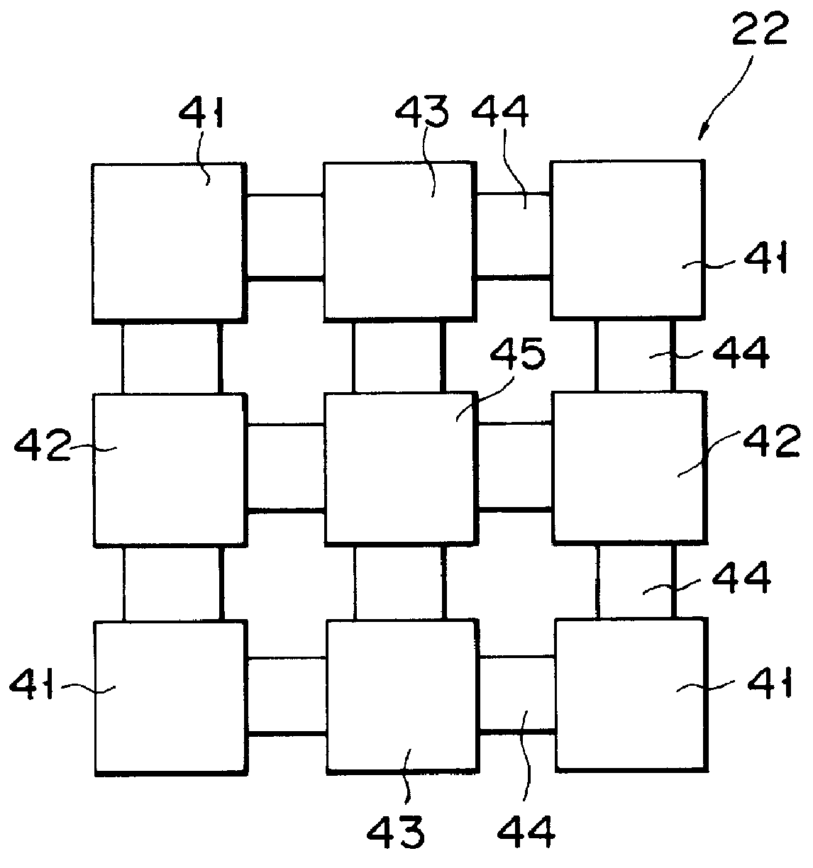
In FIG. 12 showing a scanning tunnel microscope of the third embodiment, reference numeral 110 denotes an annular support member for supporting a cylindrical three-dimensional actuator 22 on an objective lens a1 of a general-purpose microscope. The support member 110 is detachable from the outer circumferential surface of the objective lens a1 and coaxial with the objective lens a1. The support member 110 and the objective lens al are connected by, e.g., threadable engagement or bolting. The upper end of the three-dimensional actuator 22 is fixed or detachably mounted on the support member 110. A transparent plate, e.g., a probe holder 23 made of cover glass is coaxially mounted on the lower end of the actuator 22. A through hole is formed in the center of the holder 23. The proximal end of the probe 24 is inserted into this through hole, and the probe 24 is fixed in the holder 23 by, e.g., an adhesive. The probe 24 is connected coaxially with the holder 23 with high precision. In a...


PUM

PropertyMeasurementUnit
distanceaaaaaaaaaa
scanning tunnel microscopeaaaaaaaaaa
optical axisaaaaaaaaaa

Abstract

PCT No. PCT / JP88 / 00804 Sec. 371 Date Feb. 5, 1990 Sec. 102(e) Date Feb. 5, 1990 PCT Filed Aug. 12, 1988 PCT Pub. No. WO89 / 01603 PCT Pub. Date Feb. 23, 1989A scanning tunnel microscope is arranged by a combination of an optical microscope and a tunnel scanning unit. The scanning tunnel unit includes a probe held to be spaced apart from a sample placed on a sample table by a predetermined interval in an axial direction, and an actuator for axially moving the sample table and the probe to a tunnel region and relatively and three-dimensionally driving the sample table and the probe. An objective lens and the probe are arranged such that the axis of the probe of the scanning tunnel unit is aligned with an optical axis of the objective lens of the optical microscope. The sample and the probe are axially moved and brought into the tunnel region, and the sample is scanned in its surface direction while the sample and the probe are finely moved in the axial direction and a tunnel current is kept constant, thereby performing an STM observation of an observation surface of the sample. The objective lens of the optical microscope is axially moved to obtain an in-focus state, and the field of the STM observation surface is observed as an optical microscopic image through an eyepiece lens.

Description

The present invention relates to a scanning tunnel microscope (STM) for causing a metal probe to come close to an observation surface of a sample as much as possible, e.g., 50 .ANG. or less to detect and measure a tunnel current flowing between the metal probe and the sample, and imaging the tunnel current.Unlike a conventional microscope, the STM can detect electrons constrained in a sample. In recent years, the STM has received a great deal of attention as a typical surface observation apparatus capable of observing atomic alignment in a real space. The principle of operation of such an STM will be described below.A probe having a sharp tip comes close to a sample surface by an z-direction actuator such that electron clouds smeared out from the sample surface slightly overlap each other, and a voltage (tunnel voltage) is applied between the probe and the sample to cause a tunnel current to flow from the probe to the sample. The z-direction actuator is servo-controlled to keep this...

Claims


Application Information

Patent Timeline
Patent Type & Authority Patents(United States)
IPC IPC(8): G12B21/00G12B21/04H01L41/09A61K31/41A61K31/433A61K31/535A61P25/02A61P27/02C07D285/10C07D417/00C07D417/12G01B7/34G01B21/30G01N27/00G01N37/00G01Q30/02G01Q60/10G01Q60/16G02B21/00
CPCB82Y35/00C07D285/10C07D417/12G01Q60/16H01L41/092H02N2/023H02N2/028G01Q30/025G02B21/002Y10S977/869A61P25/02A61P27/02H10N30/2027
Inventor SATO, CHIAKIKOSHIISHI, KIYOZOSHIGETOMI, SADAOMISHIMA, SHUZOTAKASE, TSUGIKO
Owner OLYMPUS OPTICAL CO LTD
Why Eureka
Try Eureka