Protection circuit for high speed communication

a protection circuit and high-speed communication technology, applied in pulse manipulation, baseband system details, pulse technique, etc., can solve the problems of high power dissipation in the driver, risk of damage in the driver as well as in the receiver, and achieve protection against short circuits, avoid mismatching problems in the transmission line, and easy to implement

Inactive Publication Date: 2000-10-10
TELEFON AB LM ERICSSON (PUBL)
View PDF11 Cites 2 Cited by
  • Summary
  • Abstract
  • Description
  • Claims
  • Application Information

AI Technical Summary

Benefits of technology

A further advantage of the invention is that it is applicable with both series and parallel termination scheme.
Yet another advantage is that a protection against short circuits is provided when connecting the diodes between the respective output terminal of the PECL driver and the respective wire of the transmission line.
Still another advantage of the invention is that mismatching problems in the transmission line can be avoided when connecting a first and a second capacitor in parallel with the respective diode. Hence, the circuit does not introduce any modification in the propagation of the signals.
The invention will be described in greater detail below with reference to appended drawing.
FIG. 1 shows, in a schematic circuit diagram, a first embodiment of a protection circuit according to the invention.
FIG. 2 shows, in a schematic circuit diagram, a second embodiment of a protection circuit according to the invention.

Problems solved by technology

One possible problem with a PECL driver-receiver connection is when the driver is supplied with power while the receiver is not supplied with power.
This will lead to high power dissipation in the driver and also a risk for damages in the driver as well as in the receiver.

Method used


Image

  • Protection circuit for high speed communication
  • Protection circuit for high speed communication

Examples


Embodiment Construction

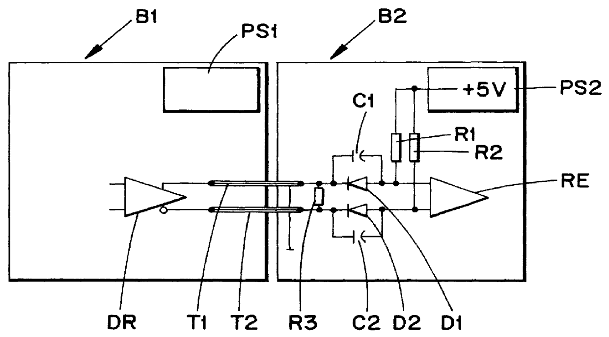
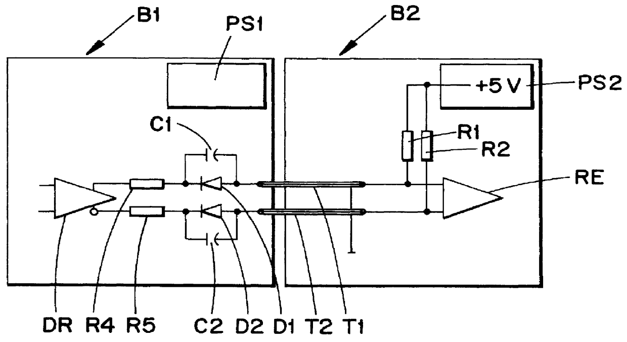
In FIG. 1 is shown a PECL driver DR with complementary outputs. The driver is transmitting high frequency signals to a PECL receiver RE via a two-wire connection T1, T2, e.g. a transmission line with a known impedance. Hereafter the two-wire connection T1, T2 will be referred to as a transmission line. The driver DR and receiver RE are arranged on different boards B1 and B2, respectively. The two-wire transmission line T1, T2 as shown in FIG. 1 is designed for arbritary long transmission lines. The receiver and driver are supplied with power from individual power supplies PS1, and PS2 located on the respective board B1, B2. In FIG. 1 a resistor R3 (normally 100 .OMEGA.) is shown interconnected between the wires T1, T2 to indicate a parallel termination of the driver.

The protection circuit according to the invention comprises two diodes D1, D2 and two resistors R1, R2.

The diodes D1, D2 are interconnected in the respective wire T1, T2 with their cathodes connected to the respective ou...


PUM


Abstract

PCT No. PCT / SE97 / 00324 Sec. 371 Date Dec. 28, 1998 Sec. 102(e) Date Dec. 28, 1998 PCT Filed Feb. 26, 1997 PCT Pub. No. WO97 / 33371 PCT Pub. Date Sep. 12, 1997Provided is a protection circuit for high speed signal communication via a two-wire connection between the two output terminals of a PECL driver and the two input terminals of a PECL receiver. The PECL driver and receiver are supplied with power from individual power supplies. The protection circuit includes two diodes connected in series with a respective wire with their cathodes electrically coupled to the respective output terminal of the PECL driver and their anodes electrically coupled to the respective input terminal of the PECL receiver, and two resistors connected between the PECL receiver power supply and the anodes of the respective diode. The resistance of the resistors ensures forward biasing of the diodes when the receiver power supply is supplying power. A capacitor may be connected in parallel with the respective diodes.

Description

The present invention relates to a protection circuit for high speed signal communication using PECL (Positive Emitter Coupled Logic) technology.DESCRIPTION OF RELATED ARTECL (Emitter Coupled Logic) devices are employed in systems requiring very fast signal processing since the power dissipation of ECL devices is constant over a wide signal frequency range. ECL devices are especially attractive for driving long transmission lines and for reduction of system clock skew (see "Designing with PECL (ECL at +5.0V)", Motorola Application Note AN1406). Integrating ECL devices in conventional TTL (Transistor--Transistor Logic) / CMOS (Complementary Metal Oxide Semi-conductor) design is sometimes desirable. Then it is advantegous to use PECL (Positive Emitter Coupled Logic) devices. PECL devices are ECL devices supplied by a positive (+5V) power supply. Thus, PECL devices can be implemented using the same power supplies as TTL / CMOS devices.PECL devices are often employed in differential applica...

Claims


Application Information

Patent Timeline
Patent Type & Authority Patents(United States)
IPC IPC(8): H03K19/003H04L25/02
CPCH03K19/003
Inventor CORVASCE, GIORGIOCALCATERRA, LUCA
Owner TELEFON AB LM ERICSSON (PUBL)
Why Eureka
Try Eureka