Display-integrated stylus detection system

a detection system and integrated technology, applied in the field of display-integrated stylus detection systems, can solve the problems of limited accuracy of light pen, adversely affecting display optics, and inconvenient display, and achieve the effect of not hindering the optical qualities of the display

Inactive Publication Date: 2000-10-17
3M INNOVATIVE PROPERTIES CO
View PDF23 Cites 205 Cited by
  • Summary
  • Abstract
  • Description
  • Claims
  • Application Information

AI Technical Summary

Benefits of technology

It is therefore an object of this invention to provide a display-integrated stylus detection system in which the optical qualities of the display are not hindered by the digitization device.

Problems solved by technology

Although light pens are useful for CRT monitors, they are not suitable for displays which do not emit light, such as LCD's, or for displays which are not refreshed by a regular, repetitive scanning sequence, such as plasma displays and LCD's.
In addition, the accuracy of a light pen is limited and it is dependent on variables such as display brightness and scan timing.
All of these devices have the disadvantage that they require an overlay of glass and / or metal films over a display device, which adversely affects display optics.
Also, the digitizer function is not inherently aligned with the display device with which it is used.
This has the disadvantage that the digitizer glass and electrodes cause optical interference with the display.
It also has significant technical and functional disadvantages.
Placement of metals and other conductive objects (e.g. the LCD display) between the stylus and the digitizer surface will decrease accuracy of the digitizer.
The large distance between the stylus and the digitizer surface will cause parallax errors in position measurements Also, noise emitted from the display will cause errors in the digitizer system.
A major problem with both approaches is that they alternate use of the electrodes between the display and position-sense functions.
Time-sharing of display drive signals in this way will result in several problems:
Reducing this time by time-sharing with another function will reduce display quality.
This sample rate is insufficient for the task, and it will be limited by the disclosed display / position signal alternating approach.
This means a display cannot be retrofitted with this technology; it must be built in.
The display driver electronics of many displays are physically integrated with the display such that addition of multiplexers is a significant mechanical problem as well.
The Nakano patent is also limited to transmitting magnetically from an X / Y matrix display and receiving in a stylus.
This method is suitable for detection of touch on a small LCD display, but it cannot be used to detect position on a large LCD with hundreds or thousands of display elements.
It has the disadvantage that it needs an overlay in front of the display to shunt the display signals in response to a touch.

Method used


Image

  • Display-integrated stylus detection system
  • Display-integrated stylus detection system
  • Display-integrated stylus detection system

Examples


Embodiment Construction

Other objects, features and advantages will occur to those skilled in the art from the following description of a preferred embodiment and the accompanying drawings, in which:

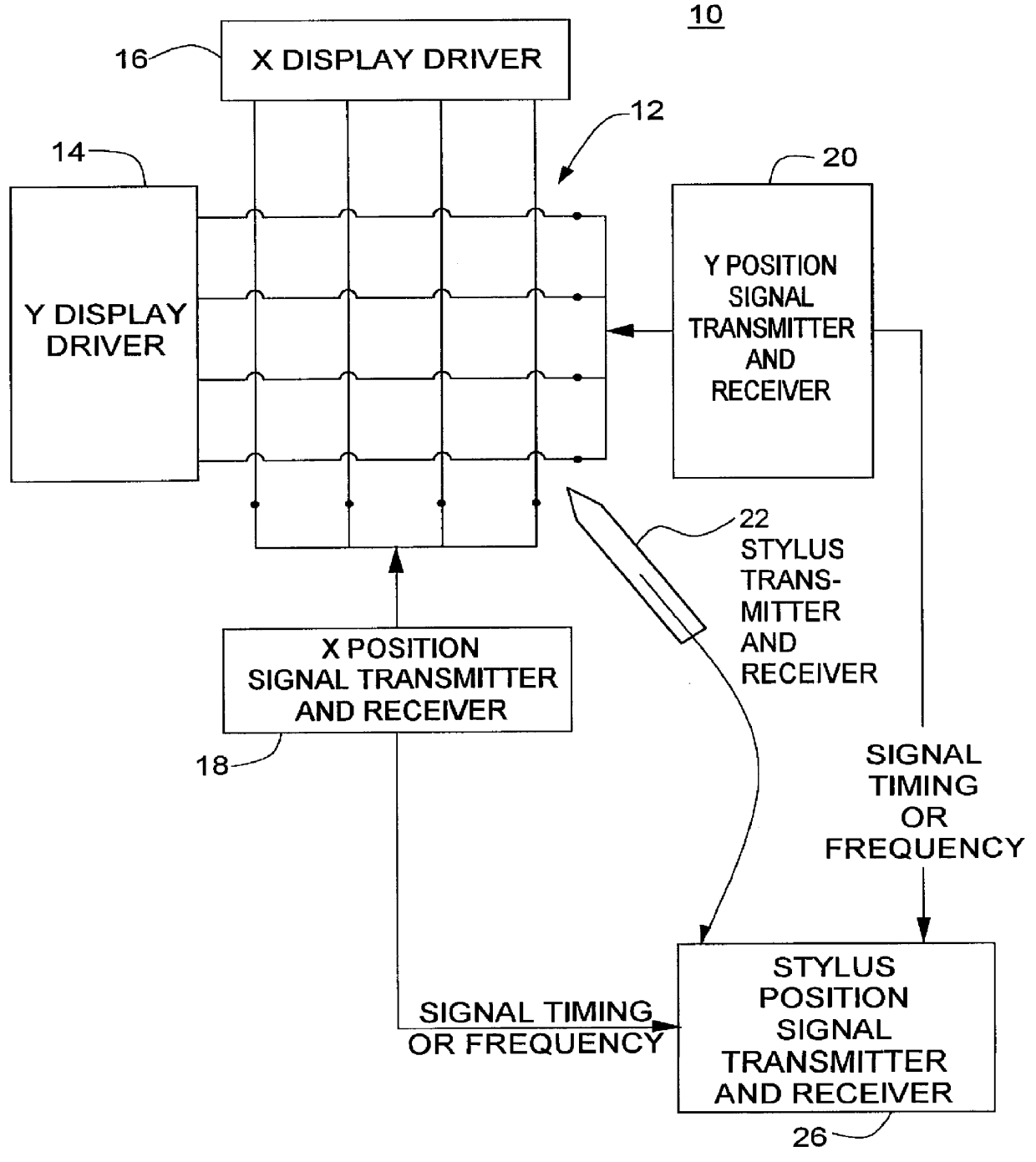
FIG. 1 is a block diagram of a display-integrated stylus detection system according to this invention;

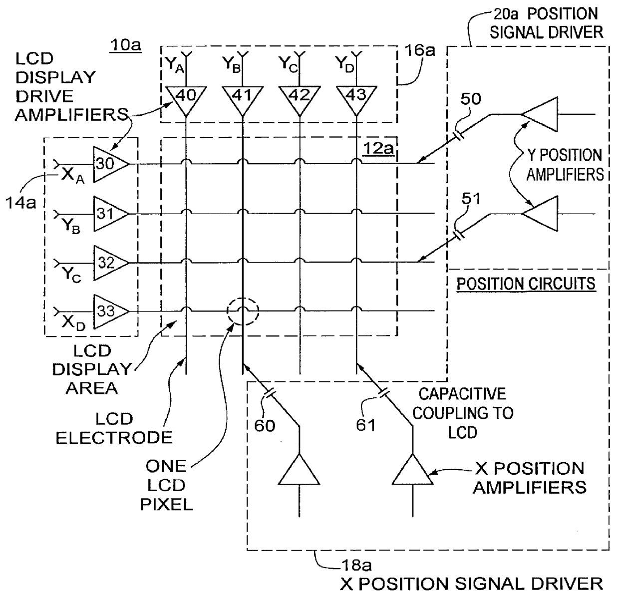
FIG. 2 is a more detailed schematic diagram of one way of implementing the system of FIG. 1 in which the display matrix can be used to either send or receive digitization signals;

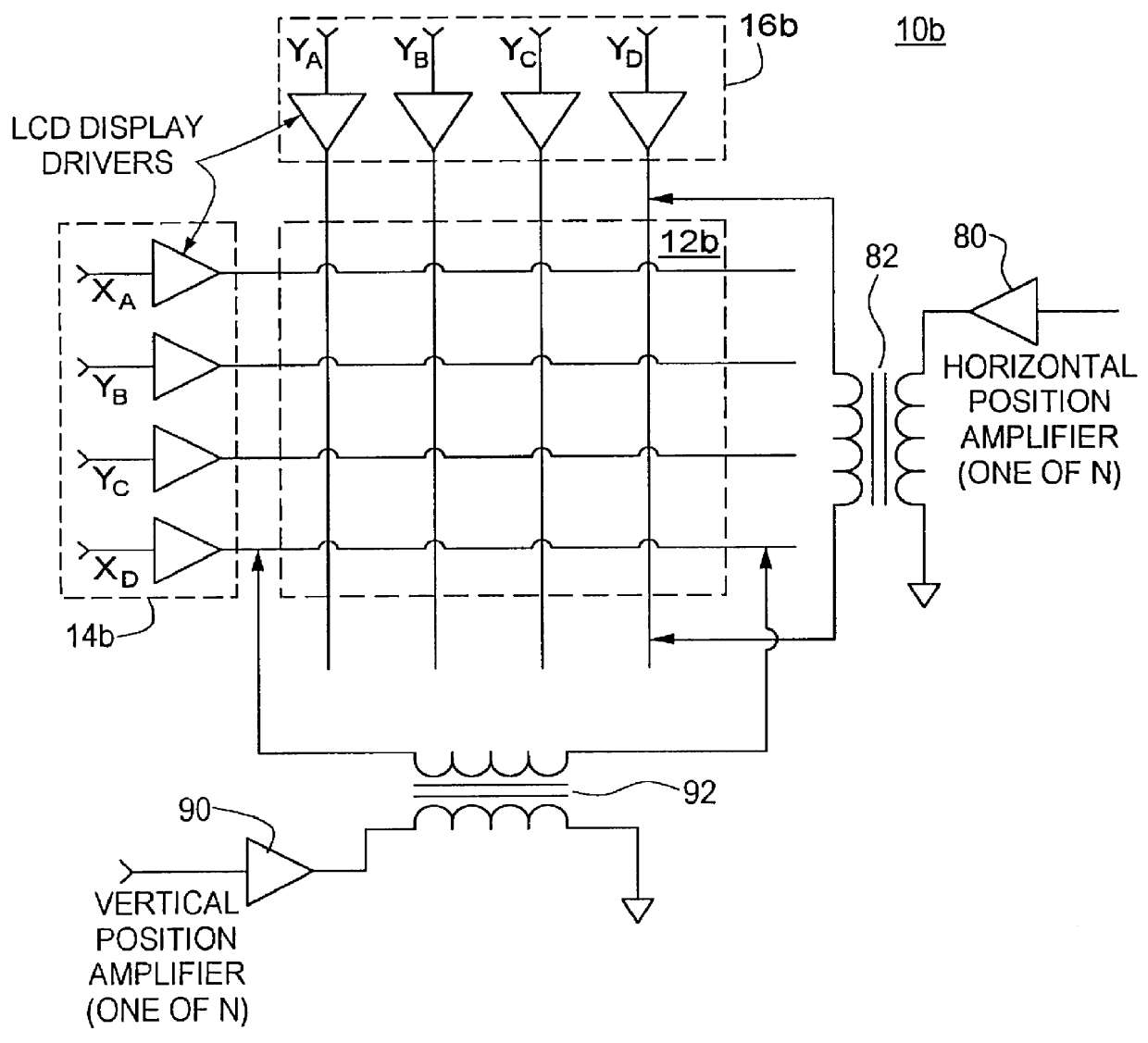
FIG. 3 is a schematic diagram of another implementation of the system of FIG. 1 in which the display matrix can also be used for either sending or receiving the digitization signals;

FIG. 4 is a schematic diagram of yet another manner of implementing the system of FIG. 1;

FIG. 5A is a schematic diagram of yet another means of implementing the system of FIG. 1 in which the display matrix is used to transmit the digitization signal;

FIG. 5B is aschematic diagram of a system similar to that of FIG. 5A, but which uses the display electrode ma...


PUM


Abstract

A system and method of measuring the position of a stylus relative to a computer information display device. The position is used to generate coordinates for the purpose of interacting with the computer. Applications may include pointing to icons on the display, picking menu items, editing of computer generated images, and feedback for input of hand drawn characters and graphics. The system uses the electrodes of the display device as part of the positioning circuit.

Description

This invention relates to a display-integrated stylus detection system that uses the display electrodes as part of the system.The task of locating a stylus with respect to a display device has been solved by a number of methods. CRT monitors have been used with light pens and touch screens for this purpose. Stylus position detection on flat panel displays has been done with touch screen technology and electronic digitizer technology. Some specific implementations are described below.Light PensA light pen senses the change in light from the CRT phosphor as the electron beam passes within the light pen's field of view. The position of the pen relative to the display is calculated by timing the pen's light detection signal versus the known time / position relationship of the CRT scanning system. Light pens have the advantage that they do not require an overlay in front of the display.Although light pens are useful for CRT monitors, they are not suitable for displays which do not emit lig...

Claims


Application Information

Patent Timeline
Patent Type & Authority Patents(United States)
IPC IPC(8): G06F3/033G06F3/041
CPCG06F3/0412G06F3/041G06F3/0442G06F3/0446
Inventor GEAGHAN, BERNARD O.
Owner 3M INNOVATIVE PROPERTIES CO
Why Eureka
Try Eureka