Method and device for diagnosis for vehicle

a vehicle and diagnostic method technology, applied in the direction of machines/engines, electrical control, instruments, etc., can solve the problems of showing abnormal values, unable to realize actual effective running conditions for other diagnoses, and wrongly diagnosing self-diagnostic items

Inactive Publication Date: 2000-10-17
HONDA MOTOR CO LTD
View PDF11 Cites 67 Cited by
  • Summary
  • Abstract
  • Description
  • Claims
  • Application Information

AI Technical Summary

Benefits of technology

It is an object of the present invention to provide vehicle diagnostic method and apparatus capable of preventing a vehicle-mounted self-diagnostic function from wrongly diagnosing a self-diagnostic item based on an actual state of a corresponding part of the vehicle even in a case where the part shows a state different from a normal state when an external diagnostic apparatus supplies the part with such a forced activation signal as to forcibly actuate the part.
According to the vehicle diagnostic method and apparatus thus configured, when an external diagnostic apparatus supplies such a forced activation signal as to forcibly actuate a part of the vehicle for an external diagnosis, and the part is expected to be actuated in a way different from a normal state, a self diagnosis related to the part expected to be actuated in the different way can be stopped, thereby preventing a self-diagnostic apparatus from causing a wrong diagnostic result due to the forced activation signal.

Problems solved by technology

The inspection process under limited conditions, however, makes it difficult to realize actually effective running conditions for some other diagnoses such as one to diagnose a function for controlling valve opening and closing timing in accordance with predetermined parameters, e.g., the vehicle running speed and / or the engine speed, and one to diagnose an evaporation system for collecting fuel gas evaporated from a fuel tank and supplying it to the engine when predetermined operating conditions are satisfied (hereinafter, referred to as an "EVP Diagnosis").
In a vehicle with such a self-diagnostic function mounted thereon, for example, when the evaporation system supplies the engine with fuel collected in a canister in response to the forced activation signal irrespective of the normal control procedure, the O2 sensor for detecting an oxygen concentration in exhaust gas may show an abnormal value, or there may be a misfiring.
This causes a problem that the self-diagnostic apparatus may wrongly diagnose a self-diagnostic item using such a detected value as a wrong parameter.

Method used


Image

  • Method and device for diagnosis for vehicle
  • Method and device for diagnosis for vehicle
  • Method and device for diagnosis for vehicle

Examples


Embodiment Construction

Referring now to the drawings, the present invention will be described in detail below.

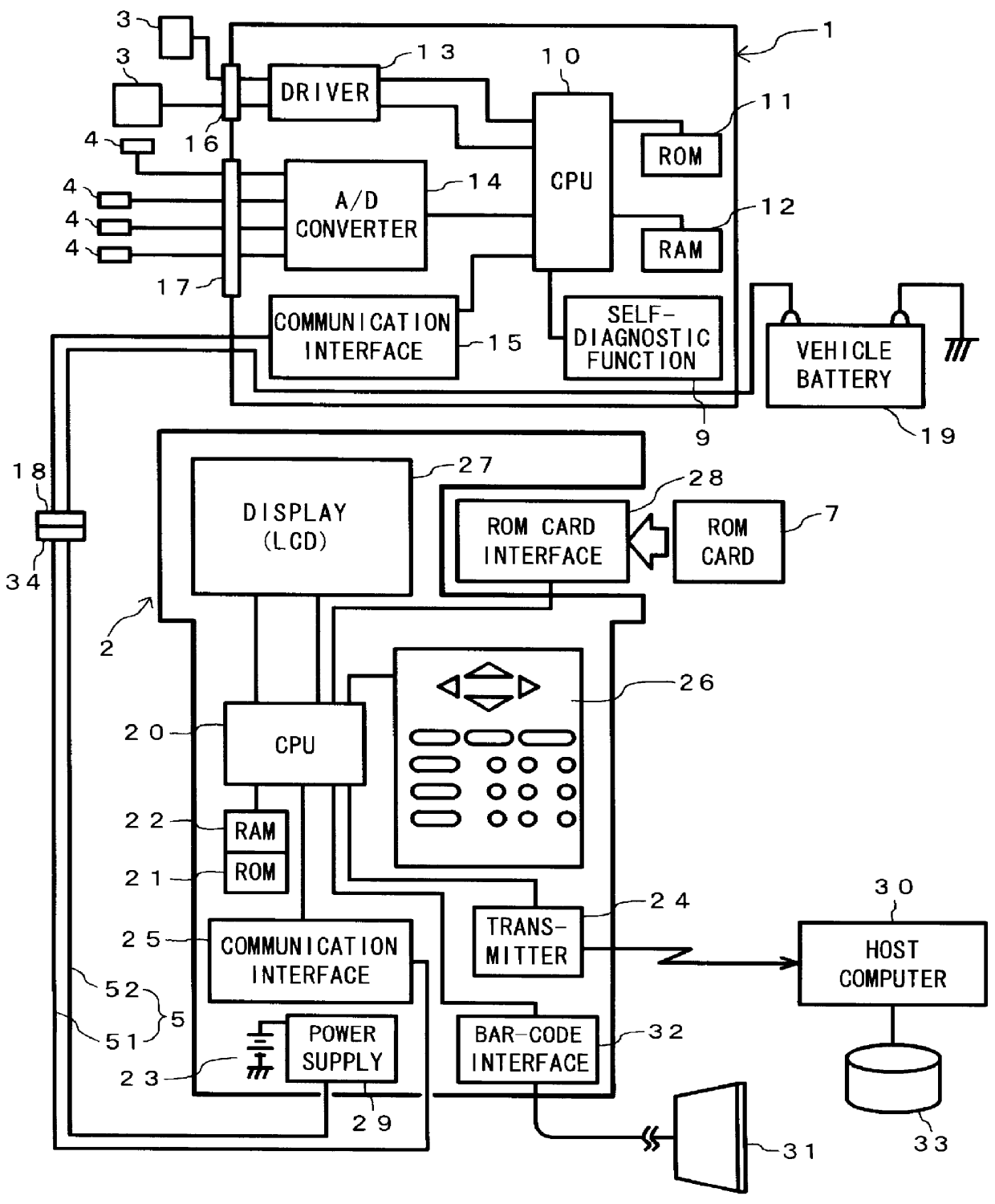
In FIG. 1, the ECU 1 is constituted of a CPU 10, a ROM 11, a RAM 12, a driver 13, an A / D converter 14, and a communication interface 15. The ECU 1 is connected to peripherals devices through connectors 16 and 17. For example, actuators 3 are connected with the connector 16, while various types of sensors and switches 4 are connected with the connector 17. The ECU 1 is also connected by a connector 18 to a communication cable 5 of the vehicle diagnostic apparatus 2 through a connector 34.

Signals from each sensor 4 or the like are input to the ECU 1. In the ECU 1, the signals are converted by the A / D converter 14 into digital signals and read into the CPU 10. The signals read in the CPU 10 are processed with control data stored in the ROM 11 and the RAM 12 according to a control program stored in the ROM 11. The CPU 10 provides a command signal to the driver 13 in accordance with the processing resu...


PUM


Abstract

PCT No. PCT / JP98 / 00975 Sec. 371 Date Oct. 16, 1998 Sec. 102(e) Date Oct. 16, 1998 PCT Filed Mar. 10, 1998 PCT Pub. No. WO98 / 40715 PCT Pub. Date Sep. 17, 1998Forced activation signal supplier 550 supplies a forced activation signal Sx to a diagnostic target part 101 related to a diagnostic item requiring a forced activation signal. Vehicle-state detector 552 detects a current state of the diagnostic target part 101 through an ECU 1. Diagnostic element 553 compares the currently detected state of the diagnostic target part 101 with a state predicted when the forced activation signal Sx is given to diagnose the diagnostic target part 101. When the forced activation signal Sx is supplied to the part of the vehicle, self-diagnosis stopping element 554 gives an instruction to stop a self diagnosis for at least an item the diagnostic result of which may vary under the influence of the forced activation signal Sx, or to invalidate the diagnostic result.

Description

This invention relates to vehicle diagnostic method and apparatus, and in particular, to the vehicle diagnostic method and apparatus capable of preventing a vehicle-mounted self-diagnostic function from causing a wrong diagnosis result even when an external diagnostic apparatus supplies a particular part of a vehicle to be diagnosed with a forced activation signal to forcibly actuate the particular part, which diagnostic apparatus communicates with an electronic control unit mounted on the vehicle to diagnose the vehicle.To improve engine control functions, an electronic control unit (ECU) with a microcomputer has been used in recent years for executing control programs, such as control of ignition timing in an engine, control of valve opening and closing timing, and / or control of fuel injection in an electronic fuel injector (EFI) for an automobile (hereinafter, referred to as a "vehicle"). The ECU is connected to sensors, such as a temperature sensor for detecting a temperature of...

Claims


Application Information

Patent Timeline
Patent Type & Authority Patents(United States)
IPC IPC(8): B60K23/00F02D41/22G01M17/007G05B23/02
CPCB60K23/00F02D41/22Y02T10/84B60K41/004B60W50/0205B60W10/04B60W2050/0005B60W2050/0006B60W2050/021B60W2050/146B60W2510/0638B60W2510/18
Inventor SASAKI, KAZUMUNEHASHIMOTO, AKIRA
Owner HONDA MOTOR CO LTD
Why Eureka
Try Eureka