Pelagic free swimming aquatic vehicle

a technology of free swimming and aquatic vehicles, applied in special-purpose vessels, underwater equipment, vessel construction, etc., can solve the problems of literature/video available whether or not these robots contain pressure hulls, and achieve the effect of high maneuverability and efficient propulsion

Inactive Publication Date: 2000-10-31
CHARLES STARK DRAPER LABORATORY
View PDF3 Cites 89 Cited by
  • Summary
  • Abstract
  • Description
  • Claims
  • Application Information

AI Technical Summary

Benefits of technology

The invention results from the realization that a truly effective pelagic free swimming aquatic vehicle which is highly maneuverable and efficiently propelled can be achieved with a rigid forebody having a predetermined volume wi

Problems solved by technology

It is unclear from the limited literature/video availa

Method used


Image

  • Pelagic free swimming aquatic vehicle
  • Pelagic free swimming aquatic vehicle
  • Pelagic free swimming aquatic vehicle

Examples


Embodiment Construction

Other objects, features and advantages will occur to those skilled in the art from the following description of a preferred embodiment and the accompanying drawings, in which:

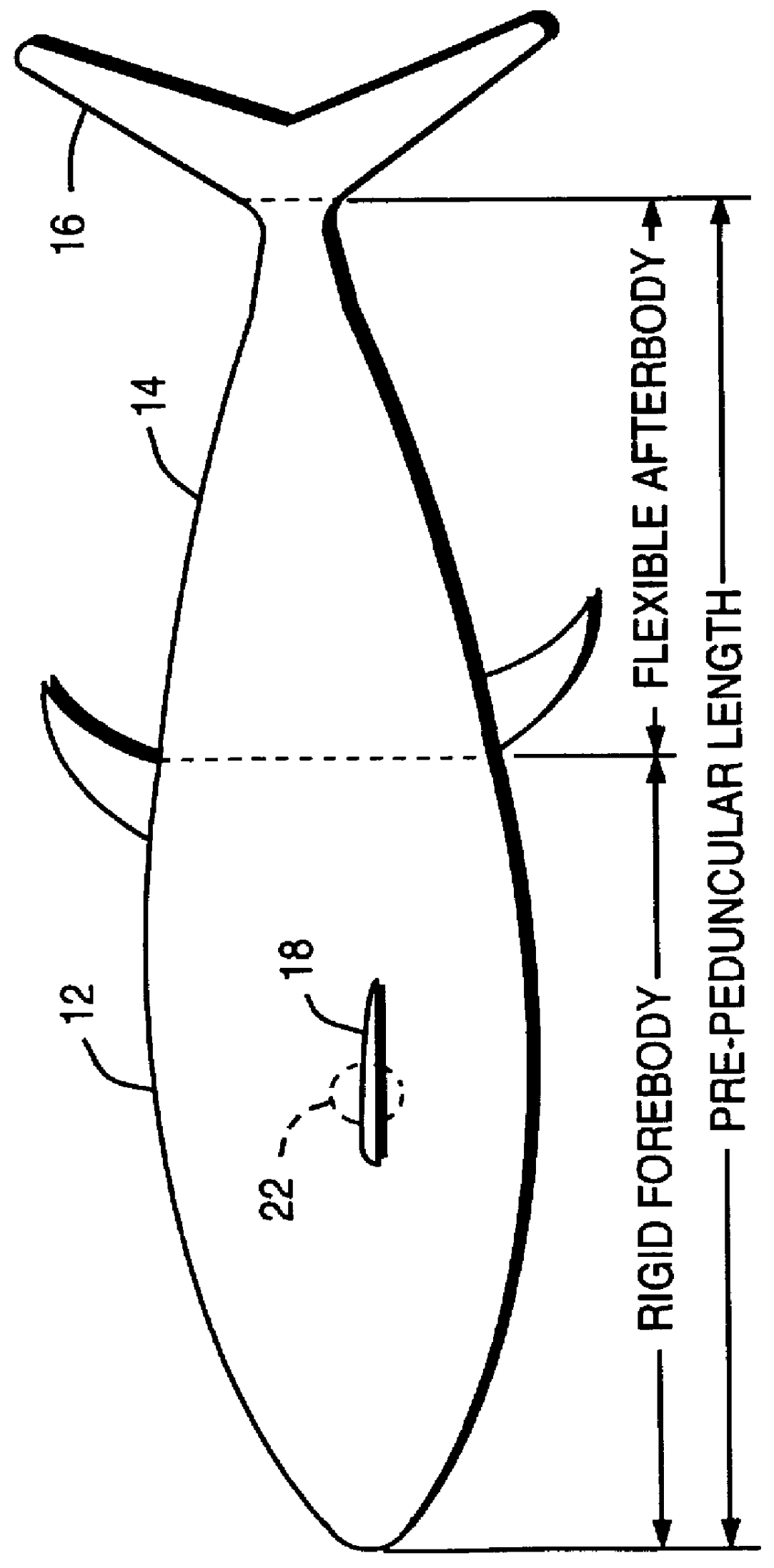
FIG. 1 is a diagrammatic side elevational view of a pelagic free swimming aquatic vehicle according to this invention;

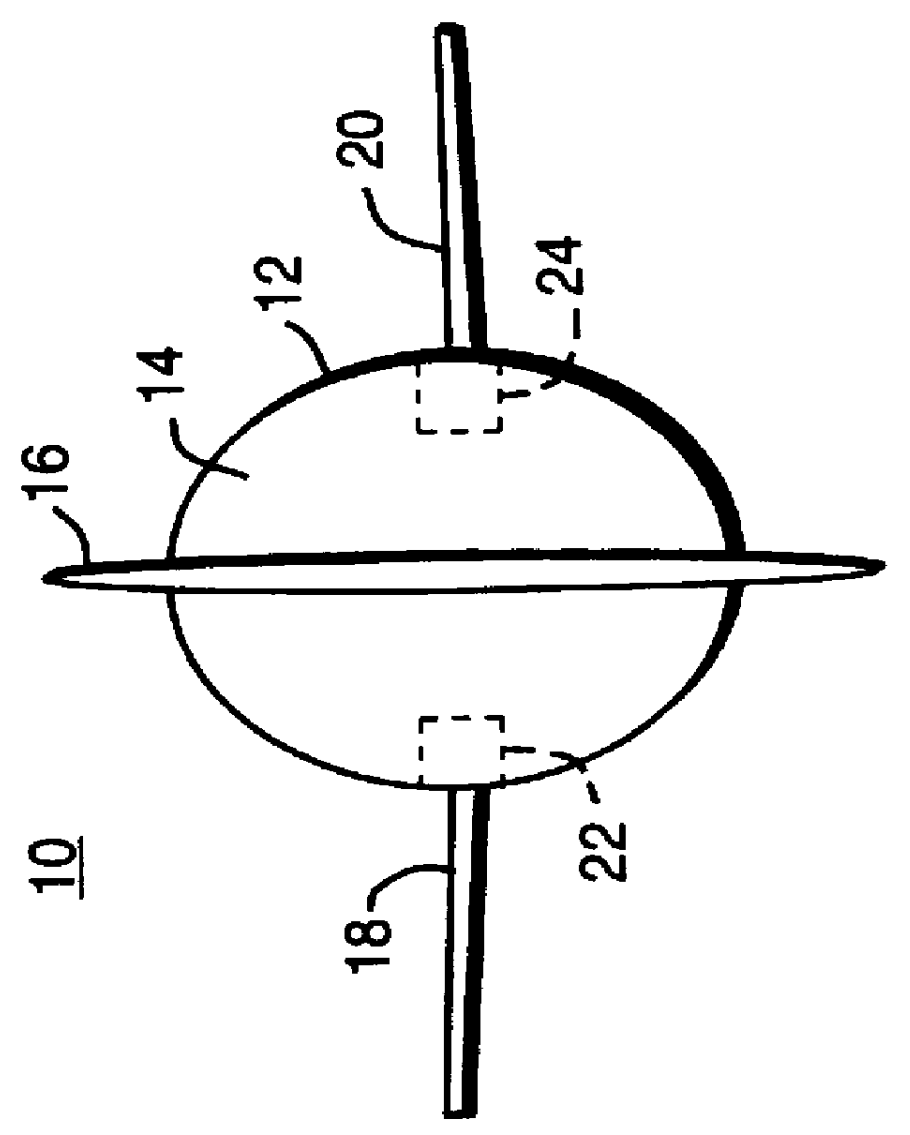
FIG. 2 is an end view of the vehicle of FIG. 1;

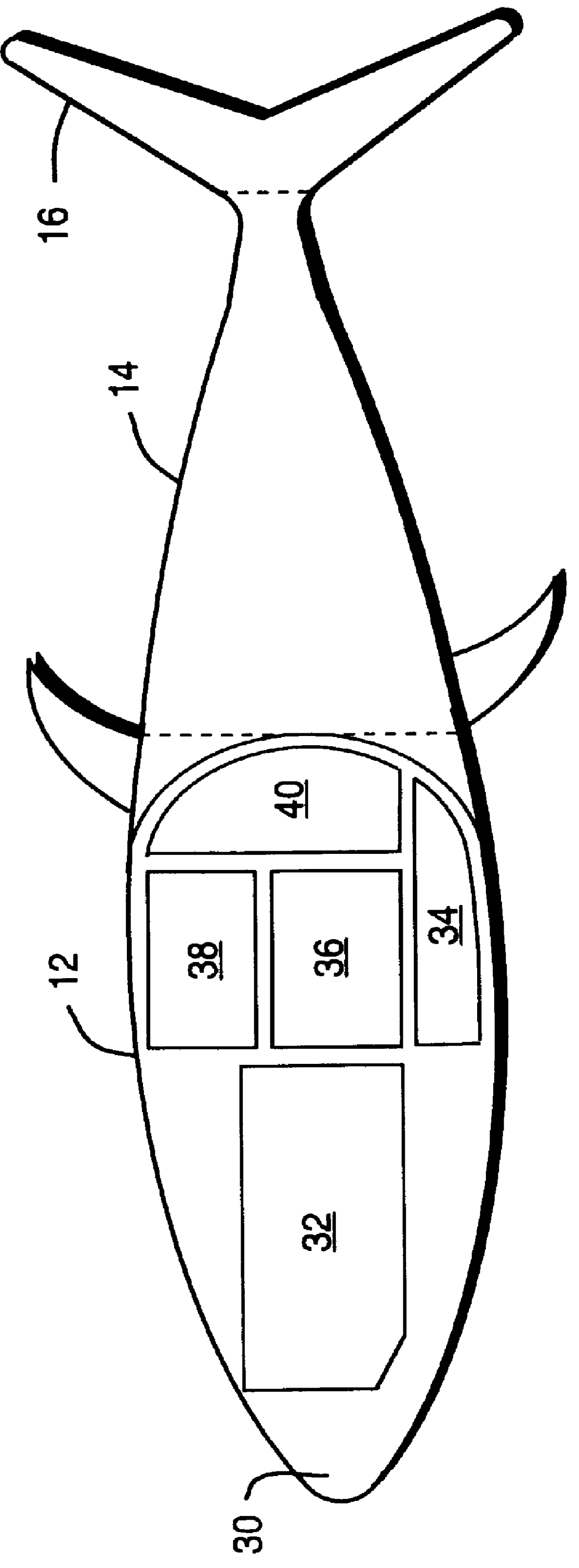
FIG. 3 is a view similar to FIG. 1 with portions of the forebody broken away to show the watertight chamber and its contents;

FIG. 4 is a three-dimensional partially broken away view of the afterbody of FIG. 1 showing the flexible batten and buoyant foam structure with the intermediate sliding plates and flexible skin;

FIG. 5 is an enlarged detailed side elevational cross-sectional view of the cupping of the flexible skin between buoyant foam plates;

FIG. 6 is a view similar to FIG. 5 showing the introduction of the sliding plates of FIG. 4 to prevent the cupping of the flexible skin;

FIG. 7 is a diagrammatic top plan view of afterbody of FIG. 1 with pa...


PUM


Abstract

A pelagic free swimming aquatic vehicle includes a rigid forebody having a predetermined volume; a watertight chamber in the forebody; and a flexible afterbody having a lesser volume than the forebody and including a maneuvering and propulsion propulsion structure and a drive system for driving the structure with a traveling sinusoidal wave motion.

Description

This invention relates to a pelagic free swimming aquatic vehicle.BACKGROUND OF INVENTIONMuch work has been done to study and imitate free swimming fish to try to effect a man-made free moving aquatic vehicle which approaches their propulsion efficiency, acceleration and maneuverability.The MIT Robotuna (Scientific American, March, 1995), is a 49-inch long biologically inspired animated tow tank test platform model built to study swimming efficiency and how it relates to body kinematics. The body shape and flexibility mimics the yellowfin tuna, a fast swimming pelagic fish similar in shape and kinematics to the renowned bluefin tuna. Robotuna was meant to be flexible in that the design allows extreme body motion combinations well beyond the capabilities of a real tuna, enabling complete access to the swimming parameter space. The robot is comprised of six cable driven links which can be independently actuated. Each link is driven by a cable which runs via pulleys through the body an...

Claims


Application Information

Patent Timeline
IPC IPC(8): B63H1/36B63G8/08B63H1/00B63G8/00
CPCB63H1/36B63G8/08
Inventor ANDERSON, JAMIE M.KERREBROCK, PETER A.SEBELIUS, PETER W.
Owner CHARLES STARK DRAPER LABORATORY
Why Eureka
Try Eureka