Guide rail and cam system with integrated connector for removable transceiver

a transceiver and integrated technology, applied in the direction of coupling device connection, electrical apparatus casing/cabinet/drawer, instruments, etc., can solve the problem of raising a number of potential connector problems

Inactive Publication Date: 2000-11-07
LUMENTUM OPERATIONS LLC
View PDF6 Cites 169 Cited by
  • Summary
  • Abstract
  • Description
  • Claims
  • Application Information

AI Technical Summary

Problems solved by technology

Miniaturizing a transceiver, however, raises a number of potential connector problems.

Method used


Image

  • Guide rail and cam system with integrated connector for removable transceiver
  • Guide rail and cam system with integrated connector for removable transceiver
  • Guide rail and cam system with integrated connector for removable transceiver

Examples


Embodiment Construction

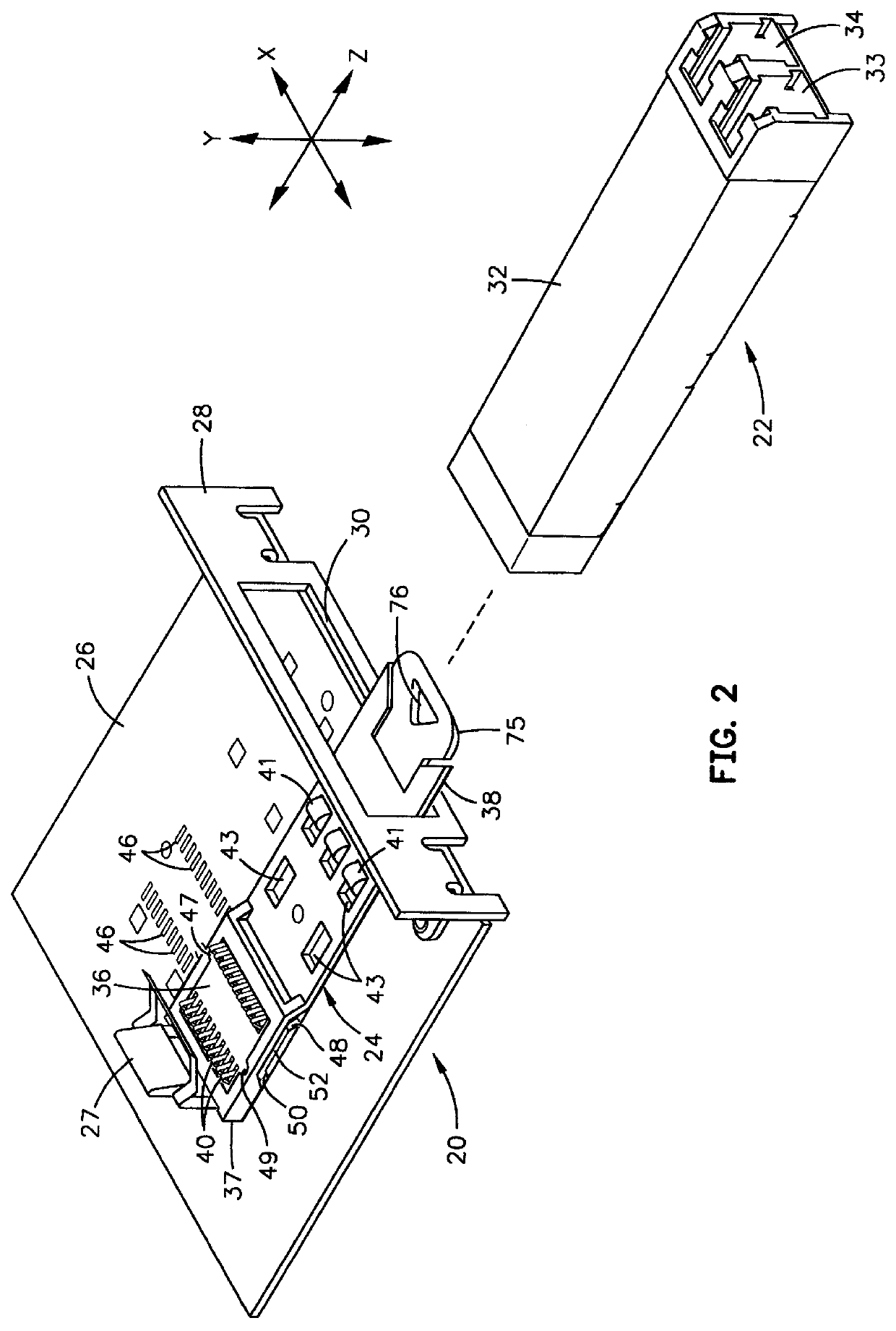
As illustrated in FIG. 2, a peripheral device port assembly 20 of a personal computer or similar device (not shown) is electrically and mechanically mateable with a data transceiver module 22. Transceiver module 22 is preferably a SFF version of the GBIC or SOC type and, as illustrated in FIG. 9, includes suitable optical transceiver electronics, such as a laser photodiode-based transmitter 21, a photodetector-based receiver 23, and suitable integrated circuit chips 25 that contain laser driver preamplifiers and other circuitry of the type conventionally included in optoelectronic transceivers. Module 22 receives and transmits serial optical data and serial electrical data, although parallel optical and / or parallel electrical transmission and reception is also contemplated within the realm of this invention. Module 22 communicates electrical signals to and from peripheral device port assembly 20 using the electrical connector system described below.

Assembly 20 includes a camming ele...


PUM


Abstract

An electrical connector system has two connectors, one of which is included in a module mateable with the other connector in a pluggable manner. The other connector includes an elongated guide rail and a connector block in which are retained two or more electrical contacts. Signal connections can be made in a predetermined sequence when the module is plugged into the other connector because the contact pads of the module are of different lengths. For example, sequencing the connection of power and ground signals with respect to data signals provides hot-pluggability. Also, a grounding contact on the module is engaged by a spring clip on the other connector to provide an additional or alternative grounding path.

Description

1. Field of the InventionThe present invention relates generally to electronic connector systems and, more specifically, to low-profile connector systems for user-removable electronic modules, such as transceiver modules that interface with a computer.2. Description of the Related ArtElectrical connectors are used to interconnect circuit cards and other electronic modules or assemblies. A connector commonly used in personal computer systems is known as a D-shell connector because the contact pins of the male connector and female connector are enclosed within generally D-shaped structures that mate to promote a secure mechanical connection as well as provide electromagnetic shielding. In a D-shell connector, contact pins of the male connector are frictionally received in contact holes of the female connector. The wiping action between the pins and holes minimizes the buildup of oxides or dirt that could impede electrical conduction. Connectors that have wiping mating parts define one...

Claims


Application Information

Patent Timeline
Patent Type & Authority Patents(United States)
IPC IPC(8): H01R13/24H01R13/22H01R13/193H01R13/02H05K1/11G02B6/42H01R13/629H05K5/00H05K5/02
CPCH01R12/57H01R13/193H05K1/117H01R13/2442G02B6/4246H05K2201/09663H05K2201/0746H05K2201/09409G02B6/4284H05K2201/094
Inventor BERG, JERRYGAIO, DAVID PETERHOGAN, WILLIAM KIM
Owner LUMENTUM OPERATIONS LLC
Why Eureka
Try Eureka