

Dual channel gas distribution plate
a gas distribution plate and dual channel technology, applied in the direction of coatings, metallic material coating processes, chemical vapor deposition coatings, etc., can solve the problems of clogging equipment components, defective devices, and achieving the alignment of holes
Inactive Publication Date: 2000-11-21
APPLIED MATERIALS INC
View PDF11 Cites 576 Cited by
- Summary
- Abstract
- Description
- Claims
- Application Information
AI Technical Summary
Problems solved by technology
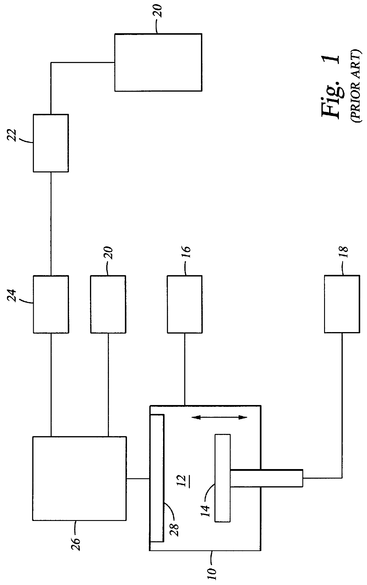
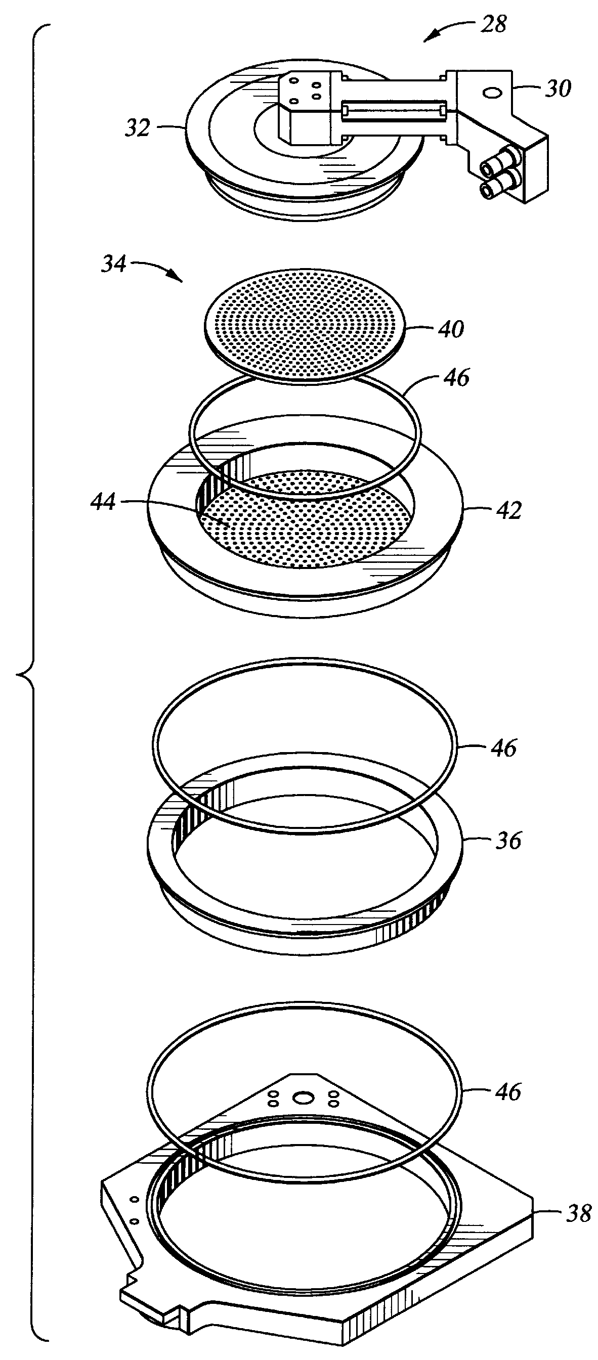
Allowing a reaction to occur at any point upstream of the processing region results in clogging of equipment components, such as the faceplate 42 and blocker plate 40 of a vacuum chamber gas distribution assembly.
Once the gas distribution plates are obstructed, the gases no longer uniformly distribute across the surface of the substrate and nonconformal deposition patterns can result, thereby producing defective devices.
One difficulty encountered with this gas plate is achieving the alignment of the holes formed within the two perforated plates.
This alignment is critical and is difficult to achieve.
Another problem is ensuring a gas-tight seal between the plates to prevent leakage between the holes.
For processes involving reactive gases, such as H.sub.2 O.sub.2 and SiH.sub.3 CH.sub.3, the resulting chemical compound clogs the gas delivery system and ultimately leads to a non-uniform deposition pattern on the substrates.
Substantial blockage may also use upstream pumping equipment and require their maintenance or replacement.
Method used
View moreImage
Smart ImageViewing Examples

Examples
example
As noted above, the present invention is particularly suited for forming SiO.sub.2 films by reacting methlysilane with hydrogen peroxide. The methlysilane and the hydrogen peroxide are delivered separately into the processing chamber. The process steps of the reaction are believed to be as follows: ##STR1##
Step 1 is performed on a cold substrate, preferably between about -20.degree. C. to 25.degree. C., to yield a silanol-type compound. Step 2 describes a condensation reaction wherein a conformal porous SiO.sub.2 network is achieved. The substrate is then heated to dehydrate the films and form a porous oxide.
Login to View More PUM
| Property | Measurement | Unit |
|---|---|---|
| Separation | aaaaa | aaaaa |
Abstract
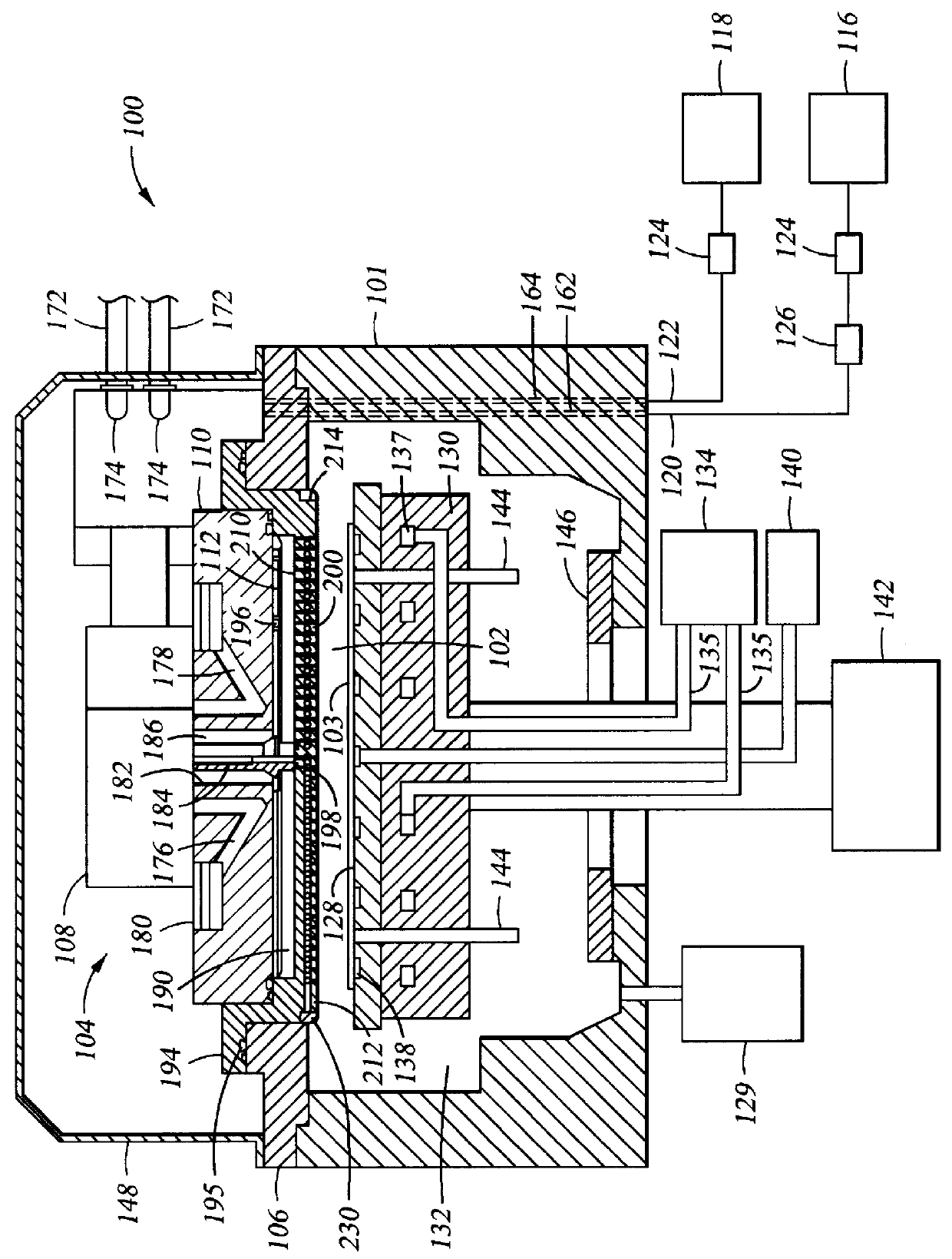
A multi-channel faceplate 200, that in some embodiments is monolithic, is provided as a portion of a gas delivery system to a process chamber 100. At least two sets of gas pathways are disposed through a faceplate and allow for independent delivery of separate gases into a process chamber 100. In one embodiment, a first gas pathway, which includes a first set of vertical channels 226, is formed through the faceplate 200. A second gas pathway includes a second set of vertical channels 228, which is formed through a portion of the faceplate and connected to a set of interconnecting horizontal channels 222 in the faceplate 200, where the second gas pathway maintains fluidic separation from the first gas pathway, prior to the gases entering the process chamber 100.
Description
1. Field of the InventionThe present invention generally relates to the field of semiconductor substrate processing equipment. More particularly, the present invention relates to a gas distribution system which provides separate and uniform delivery of two or more gases into a processing chamber.2. Background of Related ArtIn the fabrication of integrated circuits, vacuum process chambers are generally employed to process semiconductor substrates. The processes carried out in the vacuum chambers typically provide the deposition or etching of multiple metal, dielectric, and semiconductor layers on the surface of a substrate. Examples of such processes include chemical vapor deposition (CVD), physical vapor deposition (PVD), and etching processes. Many processing chambers include a gas distribution system to effectuate depositions, etching, and so forth. Dry etching of semiconductor materials can also be conducted with chemical vapor transport systems to selectively remove desired are...
Claims
Login to View More Application Information
Patent Timeline
 IPC IPC(8): C23C16/455H01L21/00C23C16/44H01L21/205H01L21/302H01L21/3065
CPCC23C16/45565H01L21/67011C23C16/45574C23C16/44
InventorMAJEWSKI, ROBERTKAO, YEH-JENWANG, YEN KUN
OwnerAPPLIED MATERIALS INC