Electronic bus system

a bus system and electronic technology, applied in the field of electronic bus systems, can solve problems such as the jeopardisation of the entire system, and achieve the effect of more reliable bus system installation and greater redundancy

Inactive Publication Date: 2000-11-21
DANFOSS POWER SOLUTIONS AB
View PDF6 Cites 80 Cited by
  • Summary
  • Abstract
  • Description
  • Claims
  • Application Information

AI Technical Summary

Benefits of technology

In view of that stated above, the object of the present invention is to provide in an electronic bus system of the type mentioned by way of introduction, spe

Problems solved by technology

A drawback of the above bus systems is that they have no redundancy, i.e. that even a small defect in the bus wire, for instance a fracture of a signal transmission wire included therein, or in a control unit connected to the signal transmission wire, may result in

Method used


Image

  • Electronic bus system
  • Electronic bus system
  • Electronic bus system

Examples


Embodiment Construction

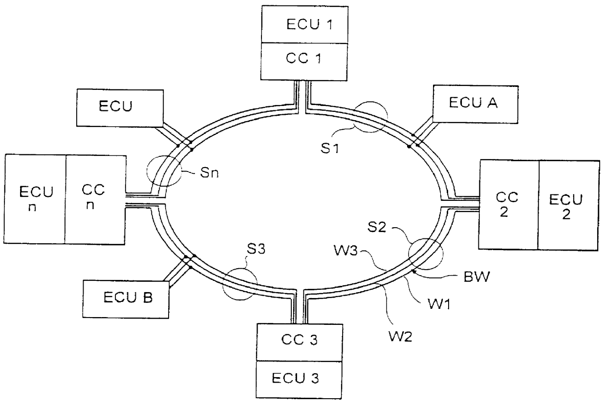
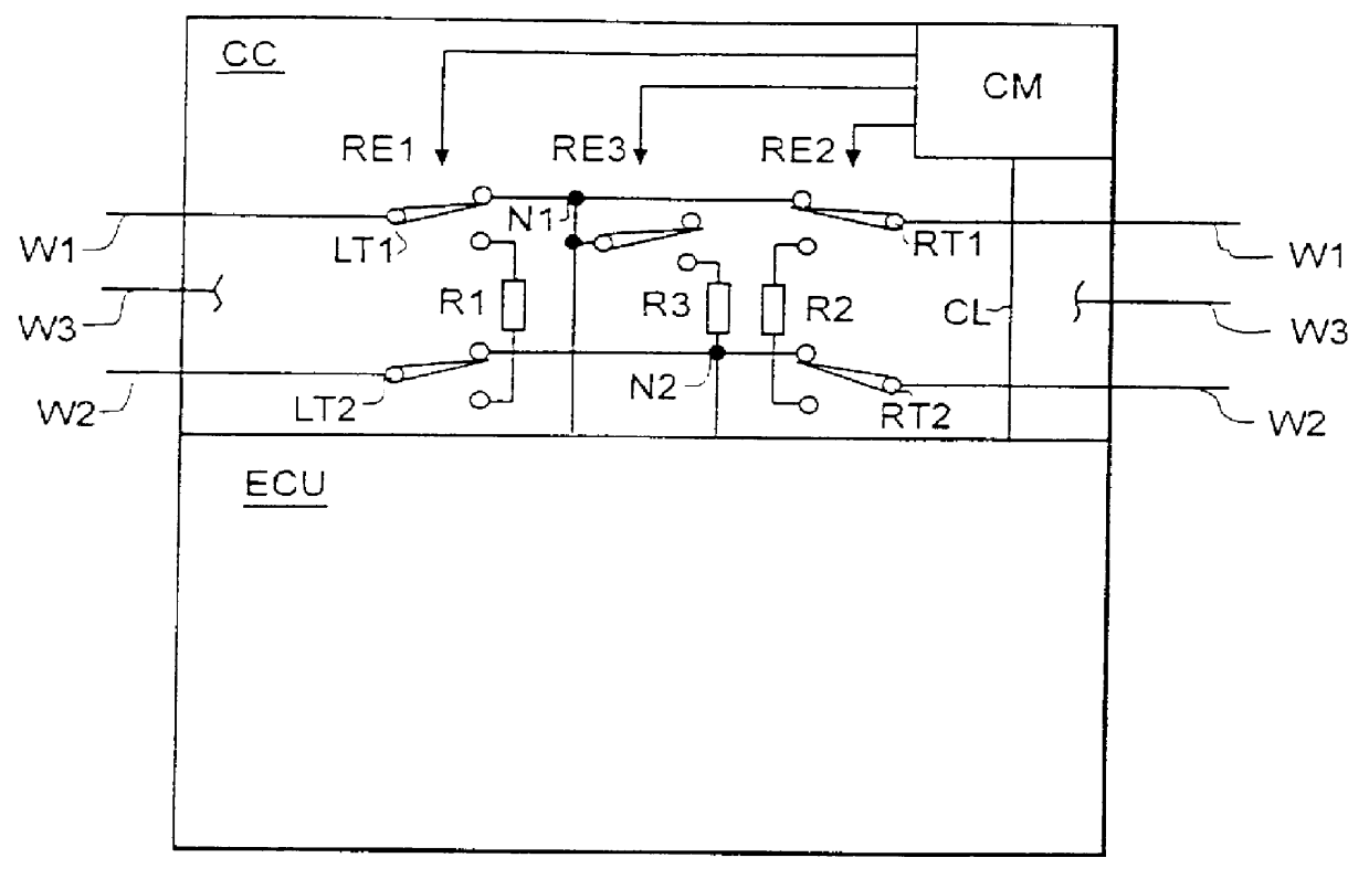
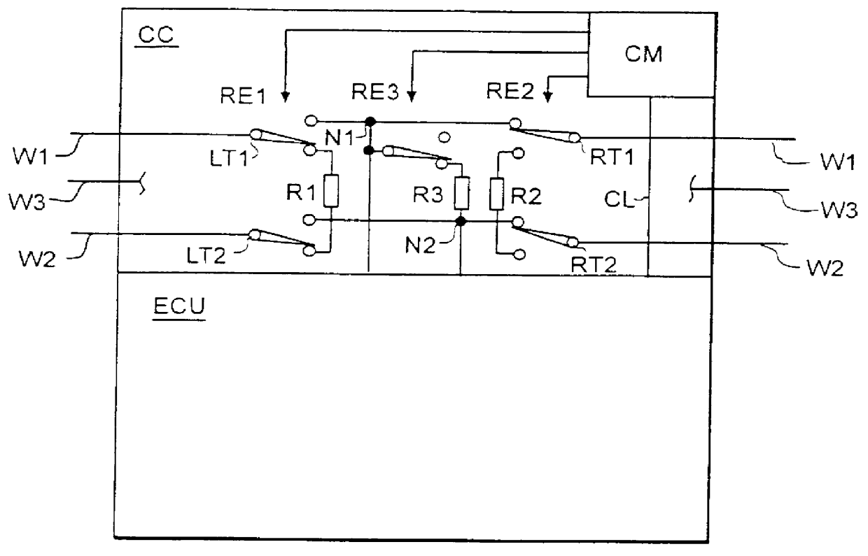
CAN is a standardised method of interconnecting electronic control units ECU to a system which is especially developed for the vehicle industry. In a CAN system, a number of electronic units ECU always exchange in a digital manner information via a bus wire consisting of a two-wire cable. The bus wire has a certain impedance about 120 ohm, which depends on the design of the cable. When a signal from a control unit ECU is transmitted on the wire, it continues along this as long as the impedance does not change. At the end of the wire there is normally a resistor, which is called terminating resistor. Without such a resistor, the signal is reflected and returns with full strength, which may cause distortion of the digital message. When the terminating resistor is correctly connected, the signal is absorbed without the arising of any reflex whatever. It is therefore important that the bus wire has a terminating resistor in both ends. The importance of these resistors besides increases ...


PUM


Abstract

An electronic bus system comprises a bus wire (BW) with at least two signal transmission wires (W1, W2) and a left and a right end, which are each defined by a terminating resistor connecting the signal transmission wires to each other. A plurality of electronic control units (ECU-ECUn) are between the two ends of the bus wire (BW) connected to the signal transmission wires (W1, W2) and are adapted, via these, to transmit and receive electric signals. The bus wire (BW) is divided into a plurality of sections (S1-Sn), which are interconnected by means of connecting circuits (CC1-CCn), and forms an annular unit. Each connecting circuit (CC1-CCn) comprises relay means, by means of which each connecting circuit, coordinated with the other connecting circuits, can connect at least one terminating resistor integrated therein, in order to define the left and/or right end of the bus wire (BW).

Description

The present invention relates to an electronic bus system for stationary or mobile applications, such as a CAN bus system for use in the process industry or in motor vehicles, said system comprising a bus wire with at least two signal transmission wires and a left and a right end, each being defined by a terminating resistor connecting the signal transmission wires to each other, and a plurality of electronic control units, which between the two ends of the bus wire are connected to the signal transmission wires and are adapted to transmit and receive electric signals via said signal transmission wires.Electronic bus systems of the above-mentioned type, especially in the form of the so-called CAN bus system, are known from, for instance, private cars, in which the electronic control units are arranged in strategically selected positions in the car, as a rule in connection with a consumer, such as a bulb, which is controlled by the adjoining control unit. This control unit cooperates...

Claims


Application Information

Patent Timeline
IPC IPC(8): H04L29/14H04L12/40H04L69/40
CPCH04L12/40006H04L69/40H04L2012/40215H04L12/42
Inventor BERNHARDSSON, STUREBJORN, FREDRIKNILSSON, GORAN
Owner DANFOSS POWER SOLUTIONS AB
Why Eureka
Try Eureka