Technique for controlling superheated vapor requirements due to varying conditions in a Kalina cycle power generation system cross-reference to related applications

a technology of kalina cycle and power generation system, which is applied in the direction of steam engine plants, machines/engines, mechanical equipment, etc., can solve the problems of premature failure of tubes, difficulty in achieving further efficiency gains in conventional, rankine cycle-based power plants, and high temperatur

Inactive Publication Date: 2000-12-05
ABB ALSTOM POWER INC
View PDF14 Cites 7 Cited by
  • Summary
  • Abstract
  • Description
  • Claims
  • Application Information

AI Technical Summary

Benefits of technology

Accordingly, it is an object of the present inventions to provide a multi-component working fluid vapor generation system, such as a Kalina cycle power generation system, capable of proper operation under conditions which vary from normal operating conditions.
It is a further object of the present invention to provide a multi-component working fluid vapor generation system, such as a Kalina cycle power generation system, capable of proper operation under varying load demands.
It is another object of the present invention to provide a multi-component working fluid vapor generation system, such as a Kalina cycle power generation system, capable of proper operation in a sliding pressure mode.
It is a still further object of the invention to provide a multi-component working fluid vapor generation system, such as a Kalina cycle power generation system, which is environmentally safe to operate.

Problems solved by technology

However, in some "aggressive" designs, this temperature can be as high as 1100.degree. F.
This effect, to some extent, explains the difficulty in achieving further gains in efficiency in conventional, Rankine cycle-based, power plants.
Without an adequate flow to the tubes 142a, the tubes can become overheated causing a premature failure of the tubes, particularly in the combustion chamber, and requiring system shut-down for repair.
Here again, without an adequate flow to the tubes 142a, the tubes can become overheated causing a premature failure of the tubes, particularly in the combustion chamber, and requiring system shut-down for repair.
Although Kalina cycle power generation test systems are in operation, no Kalina cycle power generation system is believed to have, as yet, been placed in commercial operation.
While Kalina cycle power generation test systems which are in operation may be sufficiently self-balancing over the design load range when operated under the test conditions, certain operational and / or environmental factors which arise in commercially operating power generation systems could potentially cause a dangerous system imbalance in conventional Kalina cycle power generation systems.
More particularly, commercially operating power generation systems occasionally encounter conditions which are unpredictable, and hence outside of the system design specifications.
For example, fuel, such as pulverized coal, meeting the design specification fuel grade requirements may be unavailable and therefore a different, perhaps lower grade fuel may need to be used to generate the process heat for at least limited periods of operation.
In such cases it may not be possible to generate the requisite amount of process heat with the lower grade fuel.
Extremes in the environment conditions, such as in the ambient temperature, humidity and atmospheric pressure may be experienced during certain operating periods, with the result that the temperature and pressure relationship which the system requires are unable to be met.
Additionally, unusually large and / or quick swings in load demand and hence the power generation requirements may occur, making it difficult, if not impossible, for a conventional Kalina power generation system to accomplish the necessary self-balancing in the required time frame to avoid insufficient working fluid flows within the system, e.g., insufficient superheated vapor FS 40 being, provided to the TGSS 130 and / or insufficient feed fluid 57 being provided to the boiler tubes 142a.
Accordingly, problems may arise in the operation of conventional self balancing Kalina cycle power generation systems when subjected to conditions which occasionally occur in the operation of commercially implemented power generation systems.
Although the heat balances may be satisfactory under limited operating and environmental conditions with the system operating in a constant pressure mode, under sliding pressure conditions various system anomalies are likely to occur.
For example, the heat exchanges in the exchangers 140a-140c may cause too much or too little heat to be transferred to certain flows and could even result in stream FS 5 being vaporized causing system instability, particularly in the drum type system of FIG. 5B.
As mentioned above, conventional Kalina cycle power generation systems are designed as constant pressure self-balancing systems, and hence lack active control of the fluid flows within the system.
However, as also previously noted, while this may be satisfactory under test conditions, in a commercial operating environment power generation systems occasionally encounter conditions which are outside of the system design specifications.
Such conditions are likely to make it difficult if not impossible for conventional Kalina power generation systems to accomplish the necessary self balancing in the required time frame to avoid operational problems.

Method used


Image

  • Technique for controlling superheated vapor requirements due to varying conditions in a Kalina cycle power generation system cross-reference to related applications
  • Technique for controlling superheated vapor requirements due to varying conditions in a Kalina cycle power generation system cross-reference to related applications
  • Technique for controlling superheated vapor requirements due to varying conditions in a Kalina cycle power generation system cross-reference to related applications

Examples


Embodiment Construction

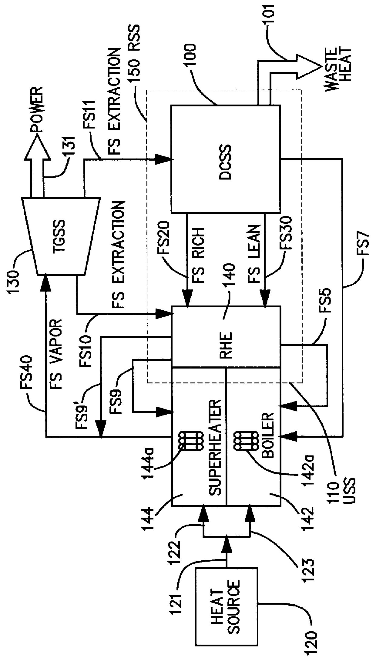
As has been discussed above and with reference to FIGS. 5A and 5B, in order for a Kalina cycle power generation system to be used in commercial implementations, the system must provide the superheated vapor flow needed by the TGSS 130 to generate the required power to meet the load demand, while at the same time providing the necessary feed fluid flow to the boiler to cool the boiler tubes 142a, even during unusual operational and / or environmental conditions which occasionally arise in commercially operating power generation systems.

More particularly, a Kalina cycle power generation system used in a commercial implementation must be operable even when subjected to unanticipated operating conditions such as operation during periods when only out of specification fuel grades are available for generating process heat, when the ambient temperature, humidity and atmospheric pressure are extreme, and / or when unusually large and / or quick swings in load demand occur. That is, the system mus...


PUM


Abstract

A method of operating a power generation system is provided. The system includes a turbine, a regenerative heat exchanger, a boiler, and a superheater. The turbine receives a stream of first working fluid and expands the first working fluid to produce power. The regenerative heat exchanger receives a stream of the expanded first working fluid from the turbine and a stream of second working fluid, for example from the RHE or DCSS of a Kalina type system. The exchanger transfers heat from the expanded first working fluid to the second working fluid to heat the second working fluid and condense the expanded first working fluid. The boiler receives and vaporizes a stream of the condensed first working fluid. The superheater receives and superheats the vaporized stream of first working fluid and the heated stream of second working fluid to form the stream of first working fluid. In operating the system, first heat is transferred from the expanded first working fluid to the second working fluid to superheat the second working fluid and condense the expanded first working fluid. Condensed first working fluid from another stream of the condensed first working fluid is combined with and thereby desuperheats the superheated second working fluid. Second heat from the expanded first working fluid is transferred to and thereby heats the desuperheated second working fluid without condensing the expanded first working fluid to form the heated stream of second working fluid.

Description

The present invention is in the field of power generation. In particular, the present invention is related to control of multi-component working fluid vapor generation systems.In recent years, industrial and utility concerns with deregulation and operational costs have strengthened demands for increased power plant efficiency. The Rankine cycle power plant, which typically utilizes water as the working fluid, has been the mainstay for the utility and industrial power industry for the last 150 years. In a Rankine cycle power plant, heat energy is converted into electrical energy by heating a working fluid flowing through tubular walls, commonly referred to as waterwalls, to form a vapor, e.g., turning water into steam. Typically, the vapor will be superheated to form a high pressure vapor, e.g., superheated steam. The high pressure vapor is used to power a turbine / generator to generate electricity.Conventional Rankine cycle power generation systems can be of various types, including ...

Claims


Application Information

Patent Timeline
Patent Type & Authority Patents(United States)
IPC IPC(8): F01K25/06F01K25/00
CPCF01K25/065
Inventor HANSEN, PAUL L.KUCZMA, PAUL D.PALSSON, JENS O.SIMON, JONATHAN S.
Owner ABB ALSTOM POWER INC
Why Eureka
Try Eureka