Stent-graft-membrane and method of making the same

a technology of stents and membranes, applied in the field of stent graft membranes and making methods, can solve problems such as varicose bleeding

Inactive Publication Date: 2000-12-05
LIFEPORT SCI
View PDF29 Cites 375 Cited by
  • Summary
  • Abstract
  • Description
  • Claims
  • Application Information

AI Technical Summary

Problems solved by technology

Portal hypertension causes blood flow to be forced backward, causing veins to enlarge, resulting in variceal bleeding.
Also, the outside surface of the implant must be biocompatible with the tissue of the blood vessel.

Method used


Image

  • Stent-graft-membrane and method of making the same
  • Stent-graft-membrane and method of making the same
  • Stent-graft-membrane and method of making the same

Examples


Embodiment Construction

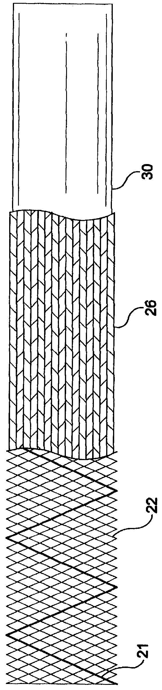
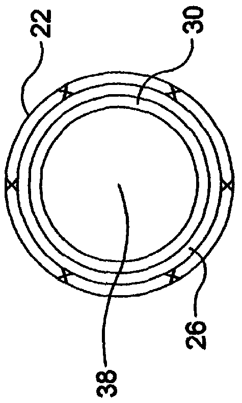
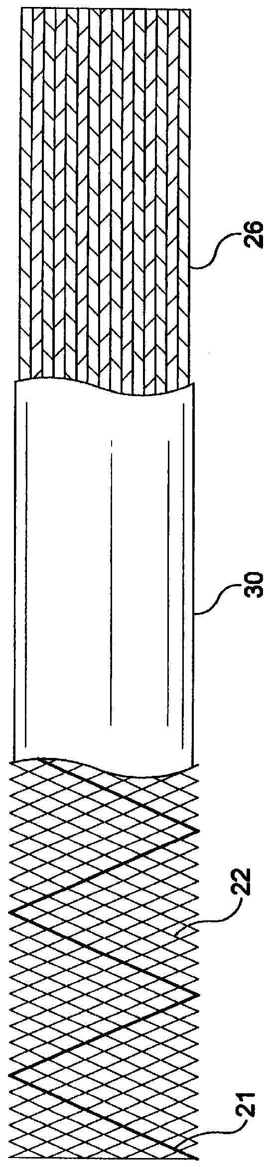
A stent-graft-membrane 20 was made by spraying silicone on a stent-graft. A 10 mm diameter and 50 mm length stent-graft comprising an Elgiloy stent and braided PET graft were bonded together with polycarbonate urethane and placed over a 10 mm diameter mandrel that was first sprayed with a TFE release agent. The mandrel and the stent-graft were placed on a rotational fixture and the motor was turned on to rotate the stent-graft. The stent-graft was coated with a volume of approximately 10 cc of a 6% solid silicone solution. The silicone solution was applied with an airbrush from a distance of approximately 8-10 cm. The solution was applied intermittently over the course of approximately 15 minutes to allow the THF and Xylene solvents to evaporate from the stent-graft surface as it was sprayed in order to prevent the graft from becoming too wet. After the silicone was applied, the mandrel and stent-graft-membrane were placed in an oven at 150.degree. C. for a period of 30 minutes to c...


PUM

PropertyMeasurementUnit
filament crossing angleaaaaaaaaaa
diametersaaaaaaaaaa

Abstract

A braided self-expandable stent-graft-membrane made of elongated members forming a generally tubular body. A membrane layer and graft layer are disposed on a endoprosthesis such as a stent. The membrane layer is substantially impermeable to fluids. The outermost layer is biocompatible with the body tissue. The innermost layer is biocompatible with the fluid in the passage. An embodiment includes a graft layer disposed on the inside of a stent and a membrane layer disposed on the outside of the stent. The innermost layer is biocompatible with the fluid in the passage. The stent-graft-membrane is used at a treatment site in a body vessel or organ where it is desirous to exclude a first fluid located outside the endoprosthesis from reaching a second fluid located in the lumen. The membrane may be made of silicone or polycarbonate urethane. The graft may be braided, woven, spun or spray-cast PET, PCU, or PU fibers. The layers may include ePTFE or PTFE.

Description

The present invention relates to a stent-graft-membrane for placement at a treatment site within a body vessel or organ to enhance and direct fluid flow therethrough and a method of making the same. More particularly, the invention relates to an implantable endoprosthesis such as a stent combined with a generally impermeable membrane layer and a permeable graft layer. The graft and the membrane provide biocompatibility with tissue at the treatment site and provide biocompatibility with fluid in the lumen.BACKGROUND OF THE DISCLOSUREIntraluminal implantable endoprostheses such as self expanding stents, grafts and stent-grafts are known and are, for example, shown in U.S. Pat. Nos. B1 4,954,126; 5,116,360; 5,133,742; 5,591,226; 5,653,747; and 5,679,470. A covered stent is described in International Publication Number WO 94 / 24961. A polyurethane is described in U.S. Pat. No. 4,810,749. A porous implantable material is described in U.S. Pat. No. 4,475,972. A method of forming an implant...

Claims


Application Information

Patent Timeline
Patent Type & Authority Patents(United States)
IPC IPC(8): A61F2/06A61F2/02A61F2/00A61F2/04A61L27/00A61F2/88A61F2/90
CPCA61F2/07A61F2/90D04C1/06A61F2/885A61F2002/041A61F2002/072A61F2002/075A61F2210/0076A61F2250/0024A61F2250/0028A61F2250/0098D10B2403/0112D10B2509/06A61F2210/0004
Inventor CHOUINARD, PAUL F.
Owner LIFEPORT SCI
Why Eureka
Try Eureka