Sieve like structure for fluid flow through structural arrangement

a structural arrangement and fluid flow technology, applied in the direction of valve housings, domestic cooling devices, heating types, etc., can solve the problems of difficulty in maintaining, repairing and retrofitting all the differently designed gas panels in a single facility, and no standard design in which gas panels are configured

Inactive Publication Date: 2000-12-12
CELERITY
View PDF25 Cites 15 Cited by
  • Summary
  • Abstract
  • Description
  • Claims
  • Application Information

AI Technical Summary

Problems solved by technology

A problem with present gas panels 100 is that most of them are uniquely designed and configured to meet specific needs.
Today there is simply no standard design in which gas panels are configured.
Uniquely designing or configuring each new gas panel costs time and money.
Additionally, the lack of a standard design makes it difficult for facilities' personnel to maintain, repair, and retrofit all the differently designed gas panels which may exist in a single facility.
The unique designs require an intensive manual effort which results in a high cost to the customer for customized gas panels.
Customized gas panels also make spare parts inventory management cumbersome and expensive.
Referring back to FIG. 1a, another problem with present gas panels is a large number of fittings 108 and welds required to interconnect all of the functional components.
The degraded finish of the heat affected zone can then be a substantial source of contaminant generation.
Also, if elements being welded have different material composition (e.g., stainless steel with inconel), desired weld geometry and chemical properties are difficult to achieve.
Thus, gas panels with large numbers of fittings and welds are incompatible wit

Method used


Image

  • Sieve like structure for fluid flow through structural arrangement
  • Sieve like structure for fluid flow through structural arrangement
  • Sieve like structure for fluid flow through structural arrangement

Examples


Embodiment Construction

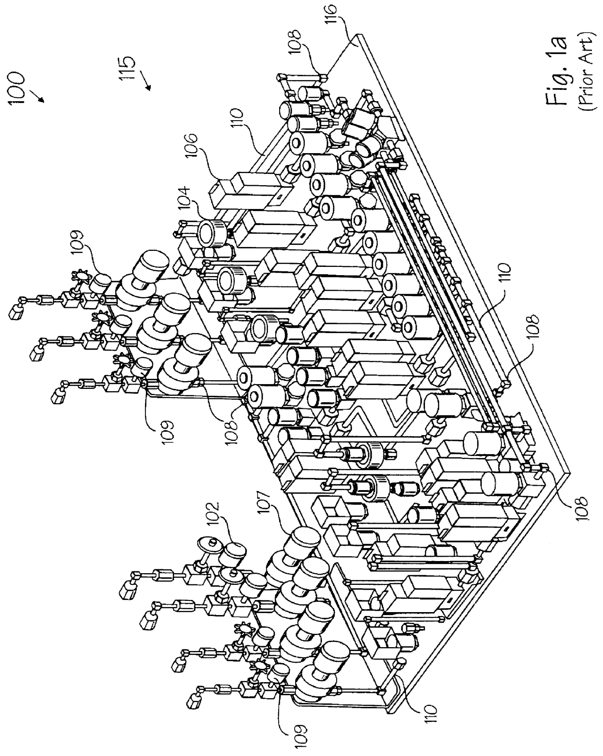
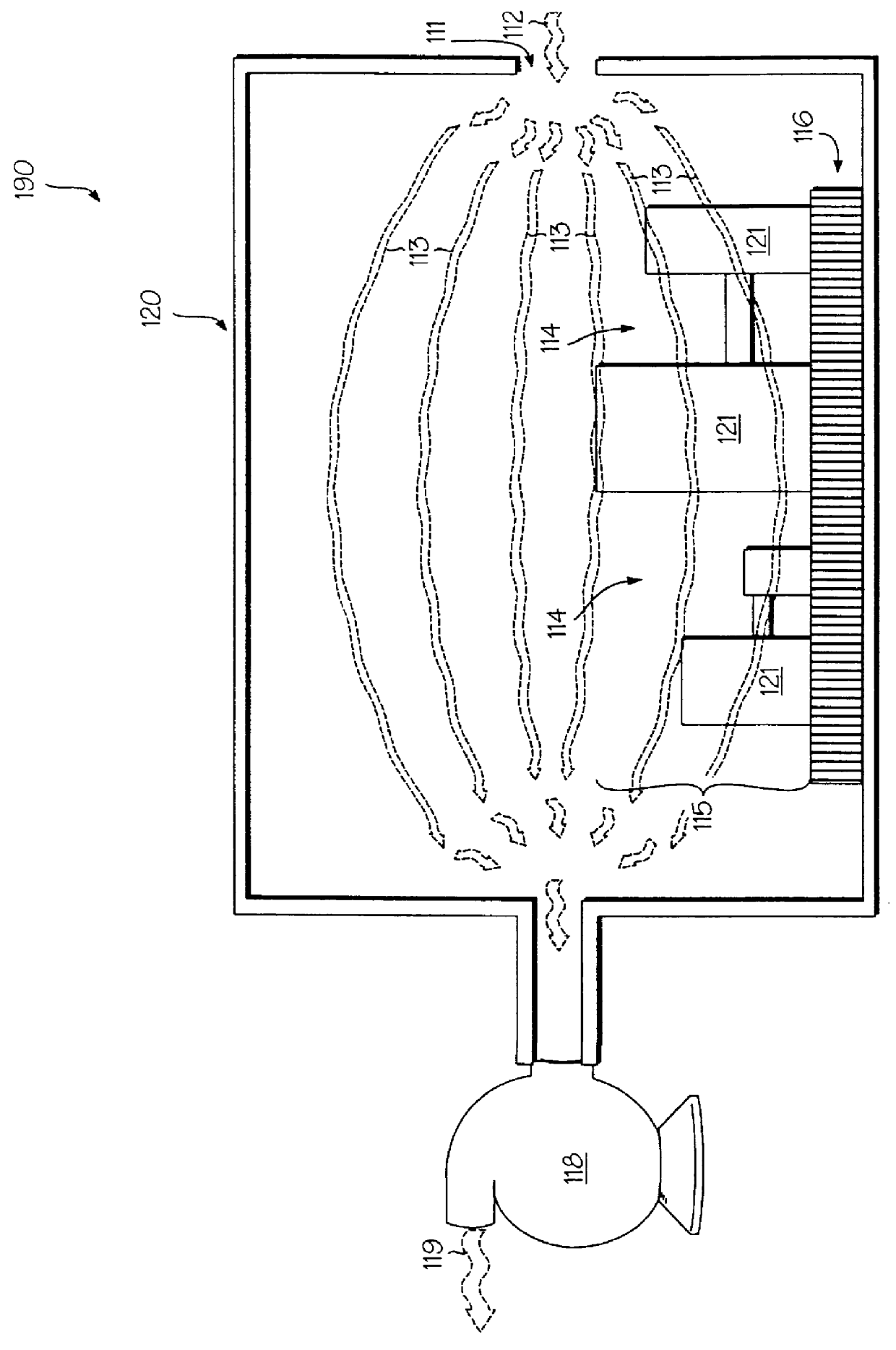
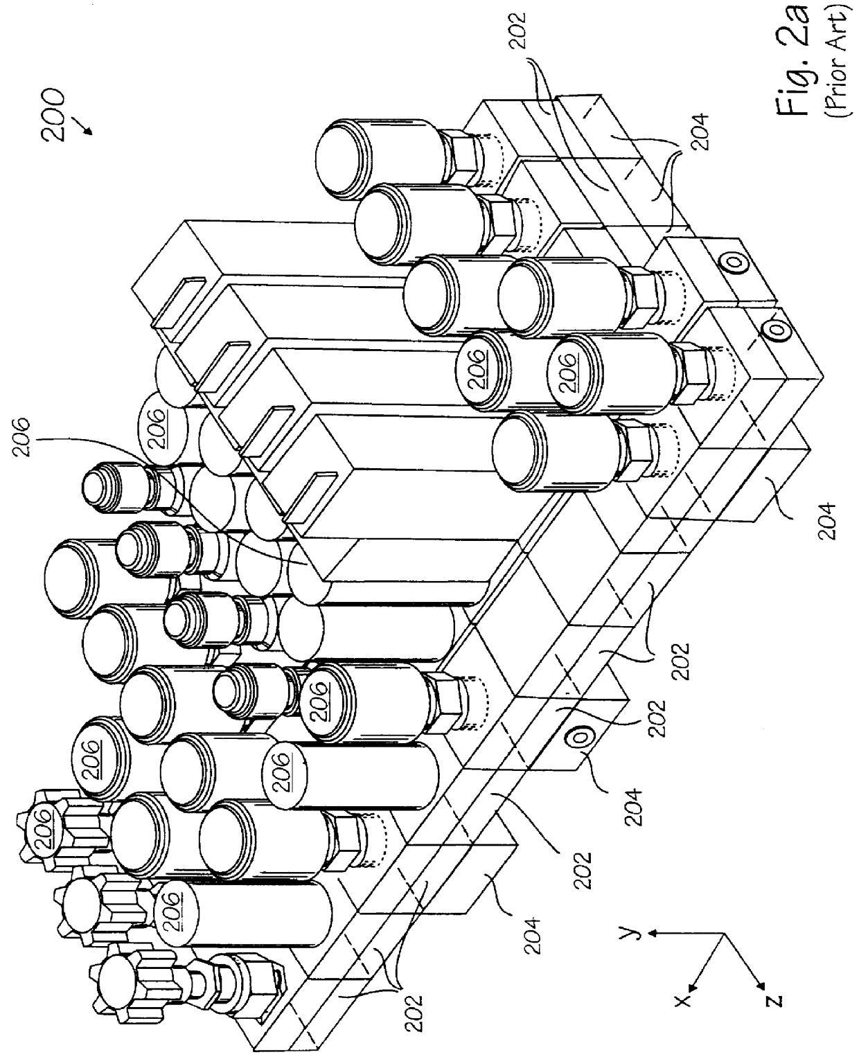
The present invention describes a novel apparatus for introducing air flow into a gas system for semiconductor manufacturing composed of interconnected modular building blocks. In the following description numerous specific details are set forth (such as particular modular building blocks, a particular mounting plane and particular direction of air flow) in order to provide a thorough understanding of the present invention. It will be obvious, however, to one skilled in the art that the present invention may be practiced without these specific details. In other instances well known mechanical assembly, machining and manufacturing techniques have not been set forth in particular detail in order to not unnecessarily obscure the present invention.

In the present invention, air flow enters an encasement entry port. The air travels through a channel to a mounting plane enter surface area. The air flow is directed through the mounting plane and then between elements of the modular gas syst...


PUM

PropertyMeasurementUnit
Lengthaaaaaaaaaa
Flow rateaaaaaaaaaa
Sizeaaaaaaaaaa

Abstract

Generally, A system for providing fluid flow through a structural arrangement is described. Specifically, a containment system for a modular gas system is described. In the present invention, air flow enters an encasement entry port. The air travel through a channel to a mounting plane enter surface area. The air flow is directed through the mounting plane and then through the modular gas system. From there, air flow is directed within an encasement towards an exit port. The air then enters a capture system which contains any gas that may have escaped the gas system and vents off purified air. In an alternate embodiment, the channel couples the gas system exit surface area to the exit port. In another alternate embodiment, the channel couples the mounting plane exit surface area to the exit port. In yet another embodiment, the channel couples the entry port to the gas system enter surface area. Additionally, many details that may apply to any of the above embodiments or an embodiment of the present invention are described. These include, a small cross sectional area entrance port to maximize intake air flow, a plugs for openings in the mounting plane that reside beneath wide gaps in the gas system, passages in the channel sidewalls to remove dead spots in the encasement, additional entrance ports to allow the removal of various dead spots within the encasement.

Description

1. Field of the InventionThe present invention relates to the field of gas delivery systems and, more specifically, to an apparatus used to trap dangerous or flammable gasses that may escape during semiconductor manufacturing.2. Discussion of Related ArtGas panels are used to control the flow of gases and gas mixtures in many manufacturing processes and machinery. A typical gas panel, such as gas panel 100 shown in FIG. 1a, is made up of literally hundreds of discreet or individual components, such as valves 102, filters 104, flow regulators 106, pressure regulators 107, pressure transducers 109, and connections 108, connected together by tens (or hundreds) of feet of tubing 110. Gas panels are designed to provide desired functions, such as mixing and purging, by uniquely configuring the various discreet components. A traditional gas panel 100 has two components: a gas system 115 and a mounting plane 116. The gas system 115 is the collection of discrete components (e.g., valves 102,...

Claims


Application Information

Patent Timeline
IPC IPC(8): B08B15/00C23C16/00
CPCB08B15/00Y10T137/0318Y10T137/5196Y10T137/87885C23C16/00
Inventor DURET, MICHAEL J.HASENKAMP, ERIN MARTINMARKULEC, JEFFREY R.REX, DENNIS G.SCHUSTER, RICHARD E.
Owner CELERITY
Why Eureka
Try Eureka