

Brake control apparatus for a vehicle
a technology of brake control apparatus and brake pedal, which is applied in the direction of brake system, brake components, transportation and packaging, etc., can solve the problems of not being able to achieve desirable high braking force, the speed of the brake pedal not becoming high enough to exceed the predetermined threshold value, and the apparatus is not effective in all cases
- Summary
- Abstract
- Description
- Claims
- Application Information
AI Technical Summary
Benefits of technology
Problems solved by technology
Method used
Image

Examples
first embodiment
a brake control apparatus according to the present invention will be described hereinafter with reference to the drawings.
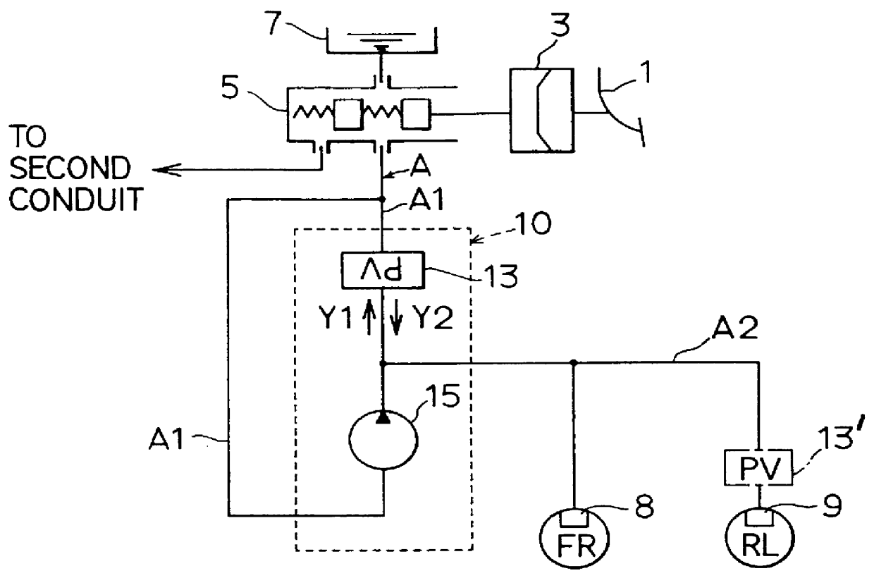
FIG. 1 is a structural view indicating the first embodiment according to the present invention. In the first embodiment, the brake control apparatus is applied in a vehicle of a diagonal brake-fluid conduit system provided with respective brake-fluid conduits of connecting front-right wheel cylinder with rear-left wheel cylinder and connecting front-left wheel cylinder with rear-right wheel cylinder in a front-wheel drive four-wheeled vehicle.
In FIG. 1, a brake pedal 1 depressed by a driver when applying braking force to the vehicle is connected to a booster 3, and depression force applied to the pedal 1 and pedal stroke thereof are conveyed to this booster 3. The booster 3 has at least two chambers, a first chamber and a second chamber. The first chamber can be set, for example, as an atmospheric-pressure chamber and the second chamber can be set as a vacuum cha...
second embodiment
(SECOND EMBODIMENT)
A second embodiment of the present invention will be described next.
In this embodiment, the brake control apparatus having the same structure as that of the first embodiment can be employed, and so the control processing thereof will be explained. It is to be noted that the same device as that in the first embodiment is given the same number in the second embodiment.
As indicated in the flowchart in FIG. 6, according to this embodiment, firstly, in step S200, it is determined whether the brake switch 23 is on. When the determination herein is affirmative, the processing advances to step S210; when the determination is negative, the processing is terminated.
In step S210, an operated quantity X indicating the present position of the brake pedal 1 is determined based on the signal from the pedal-stroke sensor 23.
In step S220, it is determined whether the operated quantity X of the brake pedal 1 is a predetermined operated quantity threshold value (starting criterion) ...
third embodiment
(THIRD EMBODIMENT)
A third embodiment of the present invention will be described next.
In this embodiment, the brake control apparatus having the same structure as that of the first embodiment can be employed, and so the control processing thereof will be explained. It is to be noted that the same device as that in the first embodiment is given the same number in the third embodiment. In the third embodiment, the control processing of the first embodiment is combined with the control processing of the second embodiment.
As indicated in the flowchart in FIG. 8, according to this embodiment, firstly, in step S300, it is determined whether the brake switch 23 is on. When the determination herein is affirmative, the processing advances to step S310; when the determination is negative, the processing is terminated.
In step S310, an operated quantity X indicating the position of the brake pedal 1 is detected based on the signal from the pedal-stroke sensor 23.
In step S315, it is determined wh...
PUM
 Abstract
Description
Claims
Application Information