Environmental test chamber fast cool down system and method therefor

a technology of fast cooling and environmental testing, which is applied in the field of environmental test chamber heating and cooling systems, can solve the problems of increasing the enthalpy of refrigerant and dropping the refrigerant, and achieve the effect of improving energy usage efficiency

Inactive Publication Date: 2000-12-19
TRIESKEY GUY T
View PDF7 Cites 37 Cited by
  • Summary
  • Abstract
  • Description
  • Claims
  • Application Information

AI Technical Summary

Benefits of technology

to provide an improved environmental test chamber refrigerat

Problems solved by technology

1. Point A to B: The refrigerant passing through the evaporator absorbs heat at an essentially constant pressure thus resulting in an increase in the enthalpy of the refrigerant. During this period the refrigerant is in the saturated region for the substantial portion of this period.
2. Point B to C: The system compressor works on the refrigerant increasing its pressure. Pressure, temperature, and thus enthalpy all increase during this period. During this period the refrigerant is in the superheated vapor region.
3. Point C to D: During this period, the refrigerant passes through the condenser that removes the heat: resulting from the working process. Thus, pressure is essentially constant while the enthalpy drops significantly leaving the superheat condition and entering the saturated region again. It should be noted h

Method used


Image

  • Environmental test chamber fast cool down system and method therefor
  • Environmental test chamber fast cool down system and method therefor
  • Environmental test chamber fast cool down system and method therefor

Examples


embodiment

Preferred Embodiment

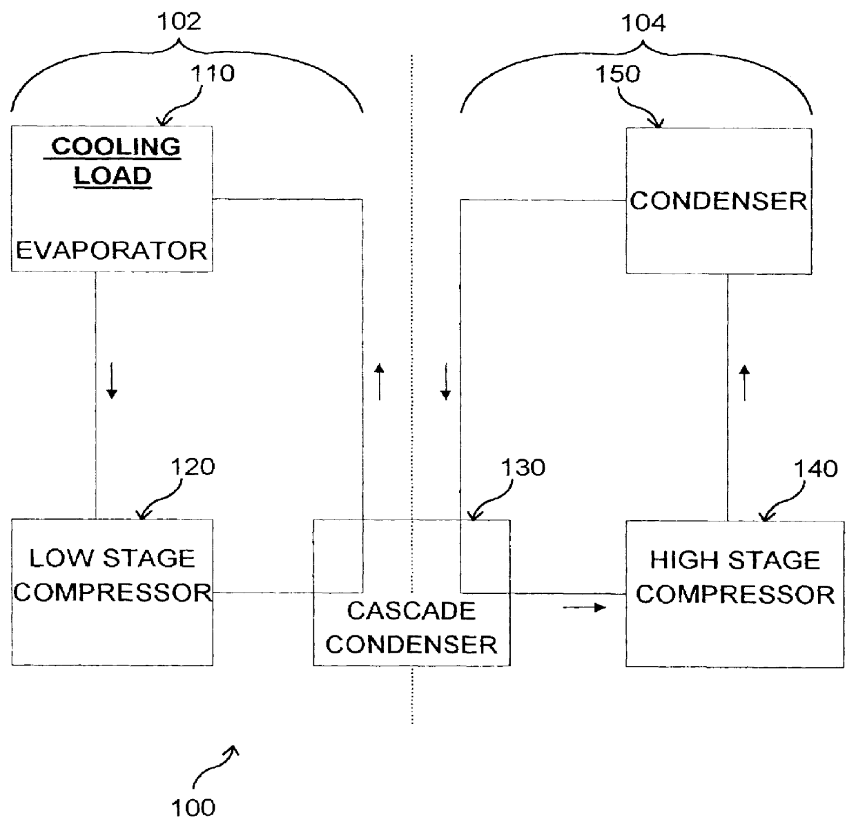
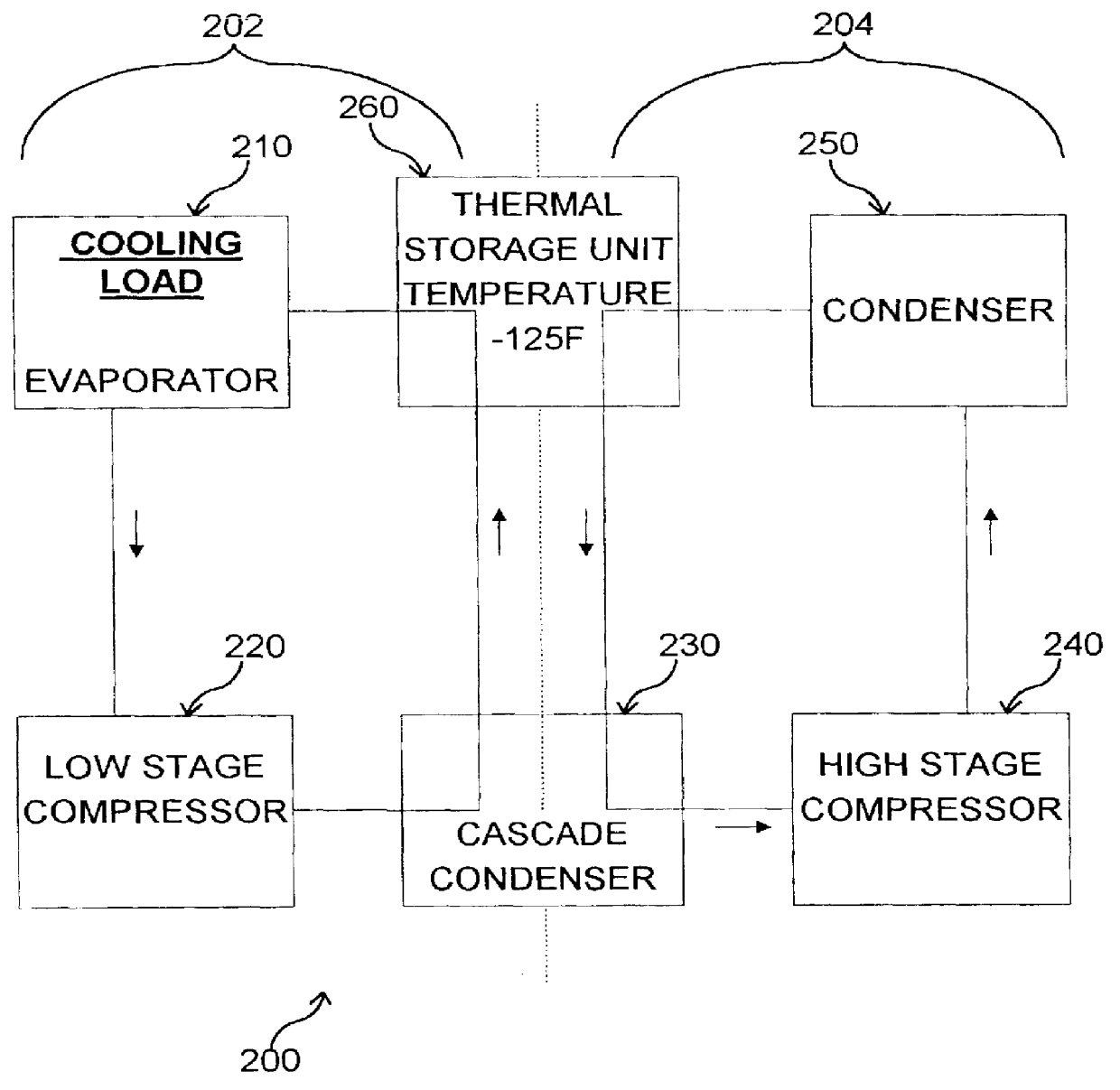
Referring to FIG. 5, a functional block diagram of a preferred embodiment environmental test chamber cascade refrigeration system of the present invention is shown. For the purposes of this discussion, additional items comprising valves and expansion valves are shown in this figure. Additional components known to those skilled in the art are not shown, but it should be appreciated that they are not eliminated from the scope of the present invention however.

The system 300 comprises low and high stage systems, or loops, as discussed in reference to FIG. 4. The low stage loop uses refrigerant R508B. The low stage loop further comprises a low stage compressor 320. The discharge of the low stage compressor 320 is coupled to a cascade condenser 334 coupled within the cascade condenser 330. The cascade condenser 334 further comprises an evaporator 332 coupled to the high stage loop. The discharge of the low stage loop from the cascade condenser 334 is next coupled to th...


PUM


Abstract

An environmental test chamber fast cool down system. The environmental test chamber fast cool down system, comprises: an environmental test chamber evaporator, a cascade condenser coupled to the environmental test chamber evaporator, a sub-cooled primary stage loop coupled to the cascade condenser, a sub-cooled secondary stage loop coupled to the cascade condenser, and a thermal storage unit coupled to the sub-cooled primary stage loop and to the sub-cooled secondary stage loop.

Description

1. Field of the InventionThis invention relates to environmental test chamber heating and cooling systems, and more specifically, to an improved method of cooling environmental test chambers using an lower capacity, smaller footprint cascade refrigeration unit in combination with a thermal storage unit.2. Description of the Related ArtEnvironmental test chambers subject components within them to a variety of physically challenging test conditions. These test conditions can include acceleration tests, sand or water tests, and temperature tests. The temperature tests can consist of not extremes of heat and cold, but also tests of large temperature change in very short periods of time. A typical environmental test chamber system for imposing large temperature changes in very short periods of time comprises either a single or twin section insulated environmental test chamber, and coupled to the environmental test chamber, a large capacity refrigeration system. A large capacity environme...

Claims


Application Information

Patent Timeline
IPC IPC(8): F25B7/00F25B5/02F25B5/00F25B40/02F25B40/00F25B9/00
CPCF25B5/02F25B7/00F25B40/02F25D2400/30F25B2400/24F25B9/002
Inventor TRIESKEY, GUY T.
Owner TRIESKEY GUY T
Why Eureka
Try Eureka