Method and apparatus for condensing and subcooling refrigerant

a refrigerant and subcooling technology, applied in the field of refrigeration systems, can solve the problems of increasing the amount of refrigerant, increasing the amount of excess refrigerant, and using additional refrigeran

Inactive Publication Date: 2000-12-19
ALSENZ INNOVATIONS
View PDF19 Cites 44 Cited by
  • Summary
  • Abstract
  • Description
  • Claims
  • Application Information

AI Technical Summary

Problems solved by technology

This method, however, requires an increased amount of refrigerant, which is undesirable.
These systems necessarily require increasing amounts of excess refrigerant to accomplish this flooding technique as the ambient temperature drops.
This results in the use of additional refrigerant, which is undesirable because commonly used refrigerants, like Chloro-Fluoro-carbons ("CFCs"), are believed to increase the ozone depletion problem in the upper atmosphere.
The additional refrigerant charge is generally lost when a leak occurs, which happens on the average several times over the life of a refrigeration system.
This extra refrigerant usage may dramatically increase the amount of leakage of CFCs from refrigeration systems.
This system ignore...

Method used


Image

  • Method and apparatus for condensing and subcooling refrigerant
  • Method and apparatus for condensing and subcooling refrigerant
  • Method and apparatus for condensing and subcooling refrigerant

Examples


Embodiment Construction

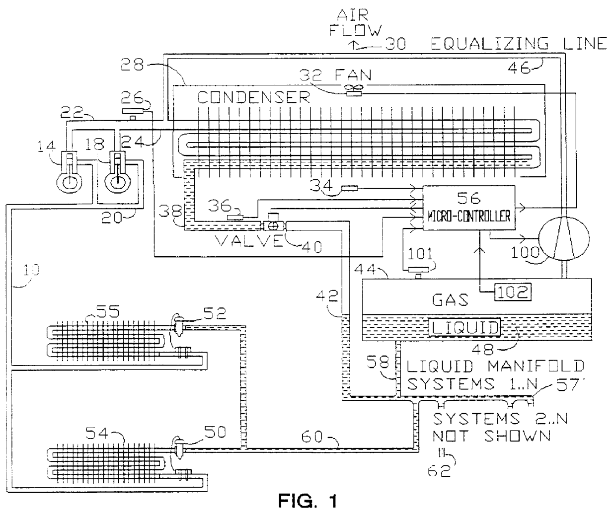
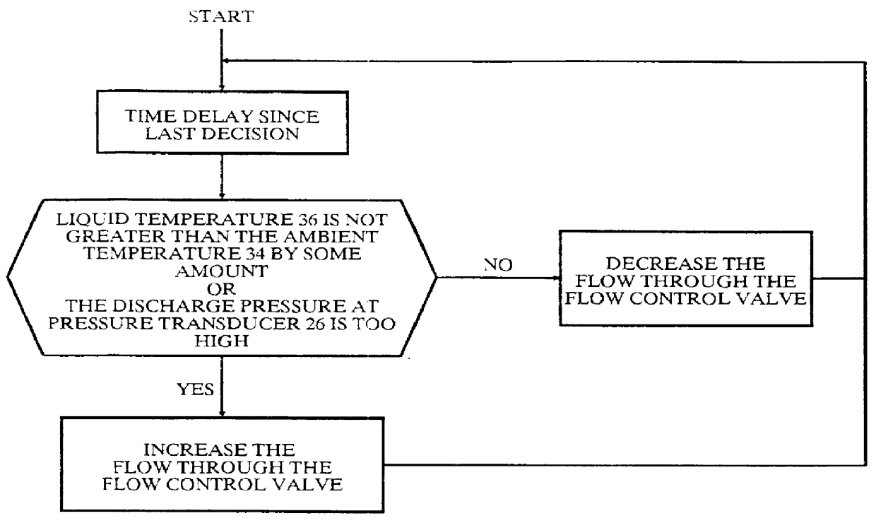
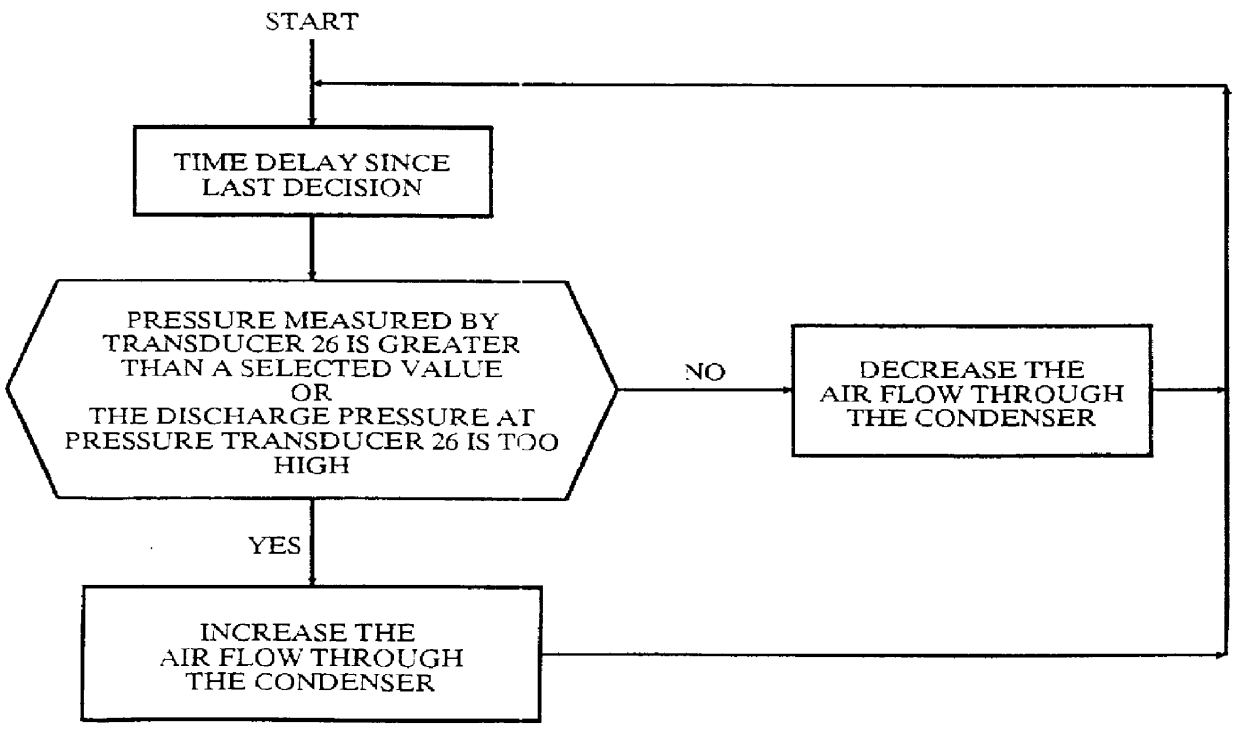
The present invention provides a refrigeration system and method wherein improved efficiency is obtained by compressing a refrigerant to a high pressure and temperature, condensing the refrigerant within a condenser, regulating the flow of condensate leaving the condenser with a flow control valve, measuring the subcooling of the condensate and controlling the condensate flow out of the condenser so as to obtain a desired amount of subcooling.

The refrigeration system of the invention includes a compressor, condenser, evaporator, and control system which provides subcooling within the refrigerant condenser by regulating the flow of the refrigerant through the condenser in a manner which always floods the condenser during normal operation. This is accomplished by not allowing the condensed liquid to leave the condenser unless it has been cooled below the condensate point. The condenser surface is allowed to drop to a temperature below the condensing temperature at the points where sub...


PUM


Abstract

This invention provides a refrigeration system which includes in a closed loop connection a compressor for compressing a refrigerant into a condenser for condensing the compressed refrigerant into a liquid refrigerant, a control valve to controlling the discharge of the liquid refrigerant from the condenser into a reservoir, a sensor for measuring the temperature of the liquid refrigerant near the control valve, a fan for circulating air thorough the condenser, a sensor for measuring the ambient temperature of the air flow through the condenser, and an electronic control system to control various functions of the refrigeration system, including the flow of the liquid refrigerant through the condenser as function of the temperature difference between the ambient temperature and the temperature of the liquid refrigerant. During operation, a minimal flooding of the condenser is always maintained; i.e., a certain amount of liquid refrigerant is always trapped to thereby subcool the liquid refrigerant before discharging it into the reservoir at all ambient temperatures. The liquid refrigerant flow is decreased when the temperature difference is greater than a predetermined value and is increased when the temperature difference is less than the predetermined value. Further improvements in efficiencies are obtained by controlling air flow through the condenser and compressing refrigerant vapors from the reservoir into the condenser.

Description

1. Technical FieldThis invention relates to a refrigeration system and more particularly to an apparatus and method for improving refrigeration system efficiencies by subcooling the refrigerant in the condenser of the refrigeration system.2. Description of Prior ArtIt has been known in the art of refrigeration systems that the net refrigerating effect in a refrigeration system can be improved by producing subcooling of the liquid refrigerant. Subcooling the refrigerant means that further energy is taken out of the liquid refrigerant, and as a consequence it does not have to be removed by the expansion process in the cooling evaporator, thus improving the overall efficiency of the refrigeration system. As an example, it has been known that when a refrigerant leaving a condenser of a refrigeration system has been accumulated in a reservoir, it can then be circulated in the liquid form through another cooling section to produce subcooling of the refrigerant at a small additional operat...

Claims


Application Information

Patent Timeline
IPC IPC(8): F25B49/02F25B40/02F25B40/00
CPCF25B49/027F25B40/02F25B2341/0012F25B2400/075F25B2400/13F25B2400/16Y02B30/743F25B2500/29F25B2600/0253F25B2600/111F25B2700/19Y02B30/741F25B2400/23F25B2700/04Y02B30/70
Inventor ALSENZ, RICHARD H.
Owner ALSENZ INNOVATIONS
Why Eureka
Try Eureka