Biological membrane voltage estimator

a voltage estimator and biological membrane technology, applied in the field of ionic current study, can solve the problems of serious destabilization of conventional rs compensation by neutralization, circuits themselves unstable, etc., and achieve the effects of easy use, increased speed, and large stability margin

Inactive Publication Date: 2000-12-19
ALEMBIC INSTR
View PDF6 Cites 50 Cited by
  • Summary
  • Abstract
  • Description
  • Claims
  • Application Information

AI Technical Summary

Problems solved by technology

The large stability afforded by this method of compensation for series resistance is due to the absence of destabilizing pipette capacitance neutralization circuits, which plague conventional designs.
Not only are such circuits themselves unstable, any residual capacitance due to imperfect neutralization seriously destabilizes conventional Rs compensation.

Method used


Image

  • Biological membrane voltage estimator
  • Biological membrane voltage estimator
  • Biological membrane voltage estimator

Examples


Embodiment Construction

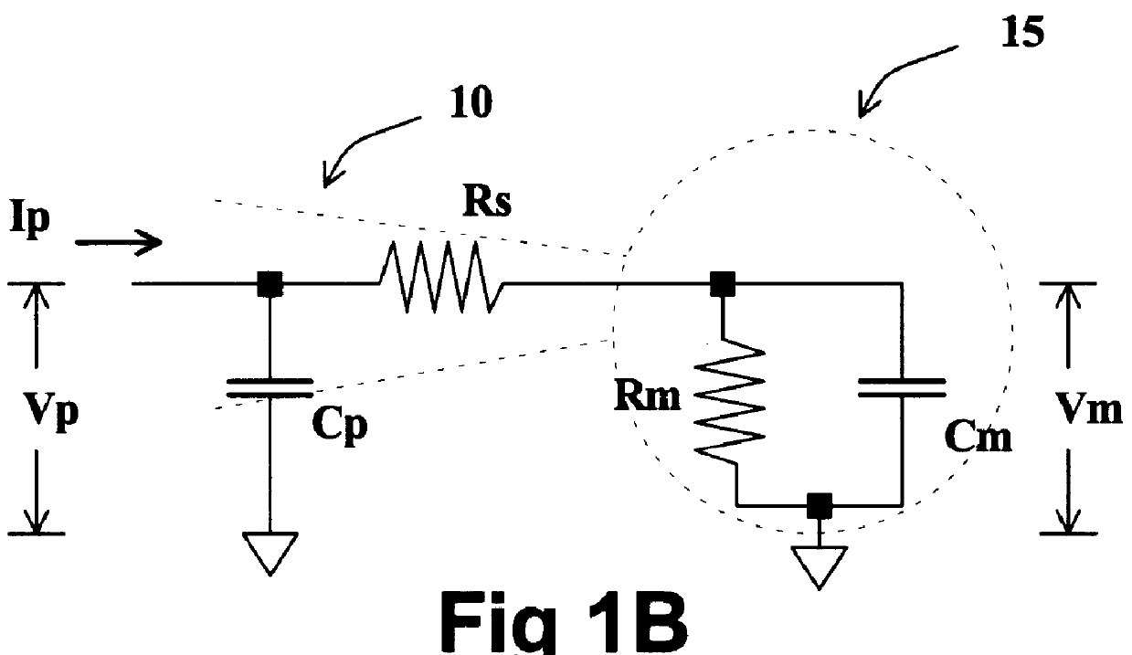
Referring to FIG. 5, the invention provides a membrane voltage estimator 70, which generates a computed membrane voltage Vmest 85 which represents the true membrane voltage Vm. Estimator 70 function is independent of cell resistance Rm or cell capacitance Cm, and does not require neutralizing the pipette capacitance Cp electronically. How estimator 70 is used to implement series resistance compensation in a single electrode voltage clamp is shown subsequently in FIG. 8.

As shown in FIG. 5, estimator 70 takes as input Ipmeas 75 and Vpmeas 80, where Ipmeas 75 is a measured signal representing the true pipette current pipette current Ip, and Vpmeas 80 is a measured signal representing the true pipette voltage Vp. Ipmeas 75 is generated by pipette current measurement means 74, and Vpmeas 80 is generated by pipette voltage measurement means 79. The fabrication of measurement means 74 and 79 are well known in the art. Estimator 70 outputs a voltage Vmest 85, which is a computed or estimate...


PUM

PropertyMeasurementUnit
voltageaaaaaaaaaa
clamping voltageaaaaaaaaaa
membrane voltageaaaaaaaaaa

Abstract

A method and apparatus for estimating the membrane voltage of a cell that is independent of cell conductance. This estimated voltage is used to implement stable, complete (100%) series resistance compensation for a single electrode voltage clamp amplifier, enabling the recording of rapid ionic currents in single, excitable cells.

Description

BACKGROUND OF INVENTION1. Field of the InventionThis invention relates to the study of ionic current due to membrane conductance changes in single cells. Much of the electrophysiology of cells--such as the generation of the action potential--is related to the flow of ionic current across the cell membrane in response to complex membrane conductance changes. To understand the electrophysiology of such cells, it is necessary measure this ionic current and characterize the membrane conductance changes.2. Description of the Prior ArtThe Voltage Clamp AmplifierAn apparatus know as a voltage clamp amplifier (VCA), in conjunction with a glass pipette electrode, is used to measure ionic current and conductance in single cells, as shown in FIG. 1A.Referring to FIG. 1A, a VCA 5 generates a command voltage Vc 41, and is connected to a cellular microelectrode, patch electrode or pipette electrode 10, the fabrication of which is well known in the art. Pipette 10 is in electrical contact with a c...

Claims


Application Information

Patent Timeline
Patent Type & Authority Patents(United States)
IPC IPC(8): C12M1/34
CPCC12M1/3407G01N33/48728
Inventor SHERMAN, ADAM JACOB
Owner ALEMBIC INSTR
Why Eureka
Try Eureka