Preamplifier with an adjustable bandwidth

a preamplifier and bandwidth technology, applied in the field of preamplifiers with adjustable bandwidth, can solve problems such as increasing design costs

Inactive Publication Date: 2001-01-16
STMICROELECTRONICS SRL
View PDF6 Cites 1 Cited by
  • Summary
  • Abstract
  • Description
  • Claims
  • Application Information

AI Technical Summary

Problems solved by technology

Lower quality displays may use these preamplifiers, but it becomes necessary in these displays to improve the connections between the preamplifier and amplifier in order to reduce the parasitic inductance, which increase the design cost.

Method used


Image

  • Preamplifier with an adjustable bandwidth
  • Preamplifier with an adjustable bandwidth
  • Preamplifier with an adjustable bandwidth

Examples


Embodiment Construction

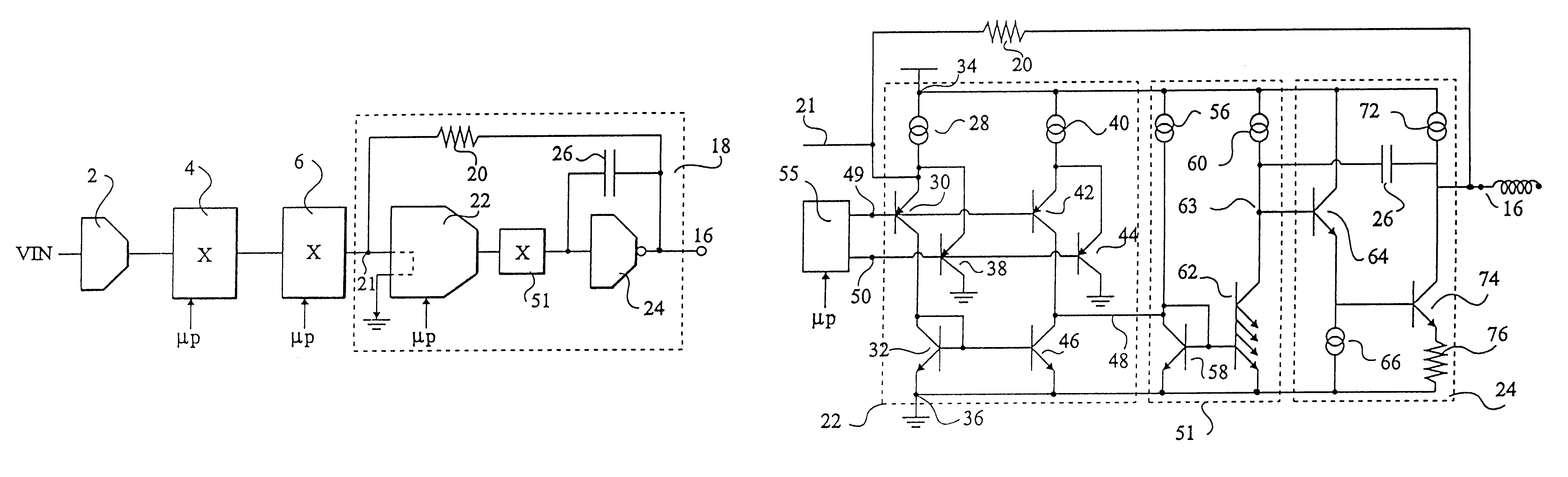
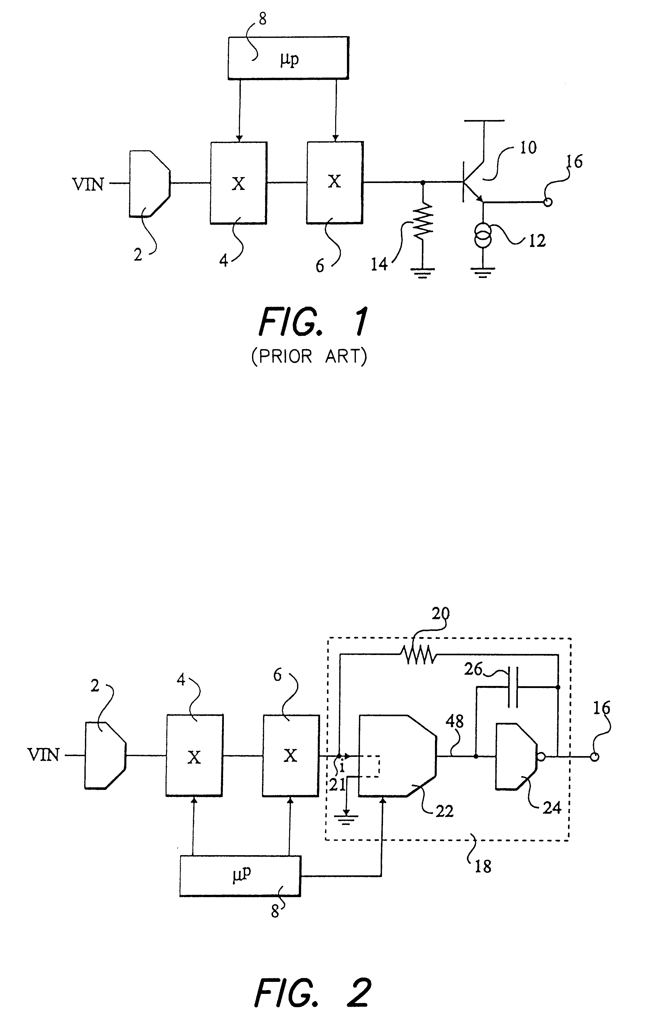
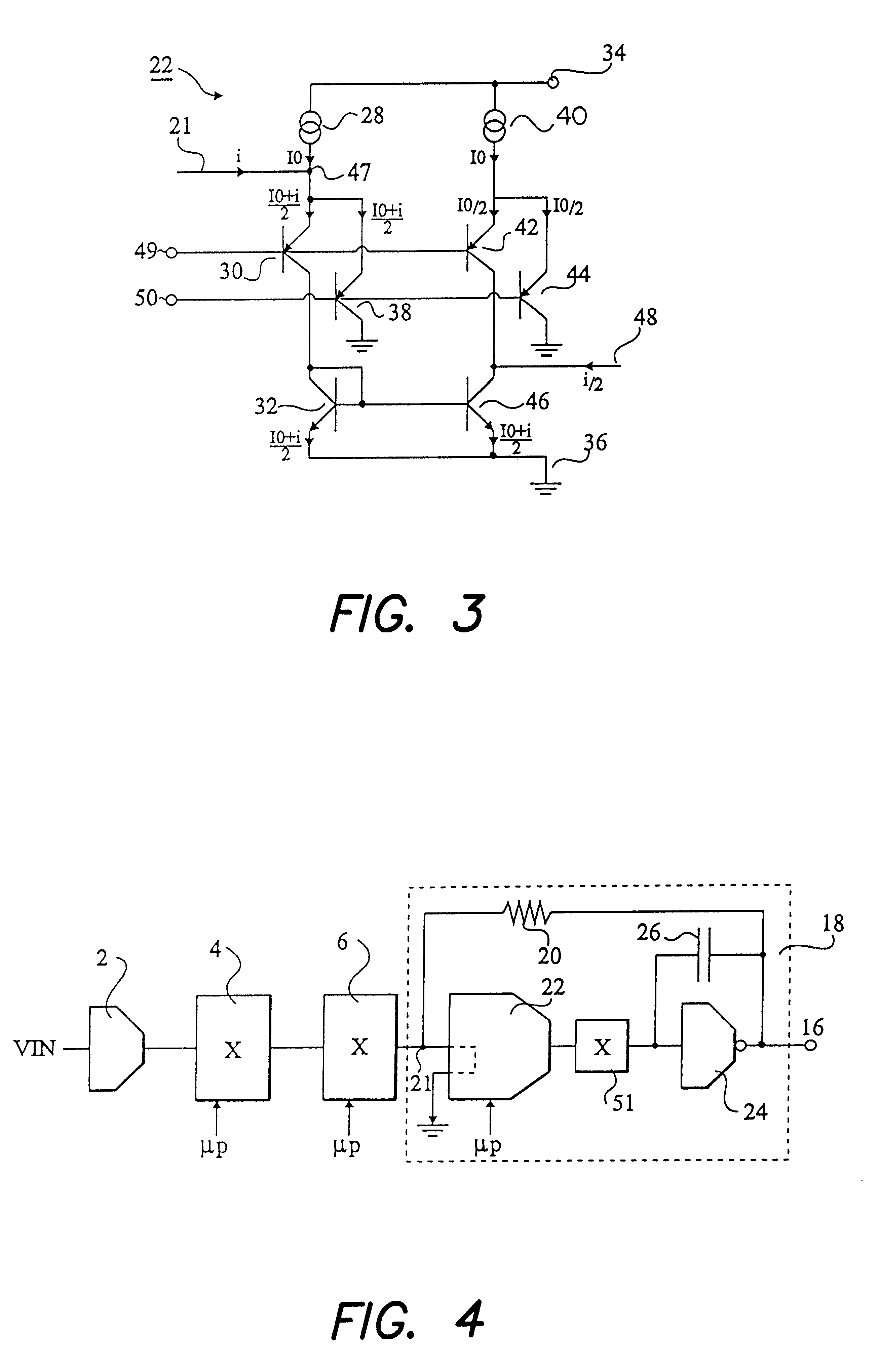
As shown in FIG. 2, a video preamplifier according to the invention includes, as in the prior art, a transconductance circuit 2 followed by two processing blocks 4 and 6 that receive control signals from a microprocessor 8. Block 6 is followed by a specific output stage 18 which is designed according to the invention to have an adjustable bandwidth, controllable by microprocessor 8, for example. The output stage 18 comprises a resistor 20 connected between its input and output terminals 21 and 16. It further comprises a current amplifier 22 having an adjustable gain followed by an inverting transconductance circuit 24. A capacitor 26 is connected between the input and output terminals of the transconductance circuit 24.

With this arrangement, it appears that the unity-gain bandwidth of the stage is proportional to the gain G of current amplifier 22. More specifically, the unity-gain bandwidth is f.sub.c =G / 2.pi.RC, where C is the value of capacitor 26 and R the value of resistor 20.

F...


PUM


Abstract

A preamplifier includes an output stage having a bandwidth which is adjustable by a control signal. The output stage includes an amplifier with an adjustable bandwidth. The amplifier includes a main input for receiving an input current, a main output for providing an output voltage, a resistor connected between the main input and output. A current amplifier with an adjustable gain is connected for receiving the input current. A capacitor is connected between an output of the current amplifier and the main output. An inverting transconductance circuit is connected between the output of the current amplifier and the main output.

Description

The present invention relates to an amplifier with an adjustable bandwidth suitable for preamplifying a video signal in CRT displays.DISCUSSION OF THE RELATED ARTVideo preamplifiers are used to process RGB video signals and to provide them to a power video amplifier that directly drives the cathodes of the tube. The processing applied to the video signals is mainly the amplification of the signal to adjust the picture contrast, the DC level adjustment in order to control the picture brightness, and the insertion of on-screen display signals in the video signal.FIG. 1 represents a conventional video preamplifier. It comprises a transconductance circuit 2 connected to receive an input voltage VIN, followed by an adjustable gain stage 4 and a DC level stage 6, controlled by an external circuit such as a microprocessor 8. An NPN output transistor 10 is connected between a power supply terminal, and a reference terminal such as ground through a current source 12. The base of the transist...

Claims


Application Information

Patent Timeline
Patent Type & Authority Patents(United States)
IPC IPC(8): H03F3/189H03G5/16H03G5/00H03G5/18H03F3/19H03G5/04H04N5/14
CPCH03F3/19H03G5/04H03G5/18H04N5/148
Inventor BAROU, MICHELCHAUSSY, DANIKA
Owner STMICROELECTRONICS SRL
Why Eureka
Try Eureka