Film applying apparatus

a film application and film technology, applied in the field of film application apparatus, can solve the problems of substrate and film part not being able to meet the requirements of film application, film in the applied state is subject to wrinkles, looseness or holding air therein, and the effective area ratio is significantly decreased

Inactive Publication Date: 2001-01-23
SOMAR CORP
View PDF16 Cites 33 Cited by
  • Summary
  • Abstract
  • Description
  • Claims
  • Application Information

AI Technical Summary

Benefits of technology

In the present invention, the preparatory bonding roll is set so that range of the elastic deforming area of the roll outer circumference at pushing the film to the substrate becomes small, thereby the preparatory bonding is performed in the state that the region liable to wrinkles, looseness and air holding is little, and other than the above-mentioned region in the preparatory bonding, in the state that the air holding is not produced, the bonding is finished by the thermal pressure bonding in the predetermined laminating rolls. Also since the laminating rolls may be provided at the position spaced from other member such as the tacking member, the outer diameter of the laminating rolls may be made sufficiently large and the film can be bonded securely.

Problems solved by technology

When the laminated film is pressure-bonded to the substrate by a pair of laminating rolls as above described, the laminating rolls are heated to the predetermined temperature (about 130.degree. C.) by means of the induction heating or the like, and since the heating of the photosensitive resin layer in the laminated film and the thermal pressure bonding to the substrate are performed simultaneously, there is a problem that the laminated film in the applied state to the substrate is subjected to wrinkles, looseness or holding an air therein.
However, when the pair of laminating rolls start the grasping of the substrate and the film, since the rubber lining applied to the outer circumference of the laminating rolls is elastically deformed mainly in the film thickness direction as above described and the deformation in the direction of pushing out an air between the film and the substrate and stretching wrinkles is little, in the range of contacting with the elastically deformed portion at the substrate grasping state, after the applying, the laminated film is liable to wrinkles, looseness or holding an air therein and this problem could not be solved even by the two-stage film applying method as above described.
Therefore when the substrate becomes very large and corresponding to this, the outer diameter of the laminating roll becomes large as above described, the range liable to the air holding or the like as above described naturally becomes large and the area of the pattern exposable region with respect to the total area of the substrate becomes little, and a problem is produced in that the effective area ratio is significantly decreased.
In this case, since it is unsuitable that the half cut line is set to the region liable to the air holding or the like, there is a problem that the substrate part and the film part not becoming the pattern exposure region increase and the waste becomes much.

Method used


Image

  • Film applying apparatus
  • Film applying apparatus
  • Film applying apparatus

Examples


Embodiment Construction

Embodiments of the present invention will be described in detail referring to the accompanying drawings as follows.

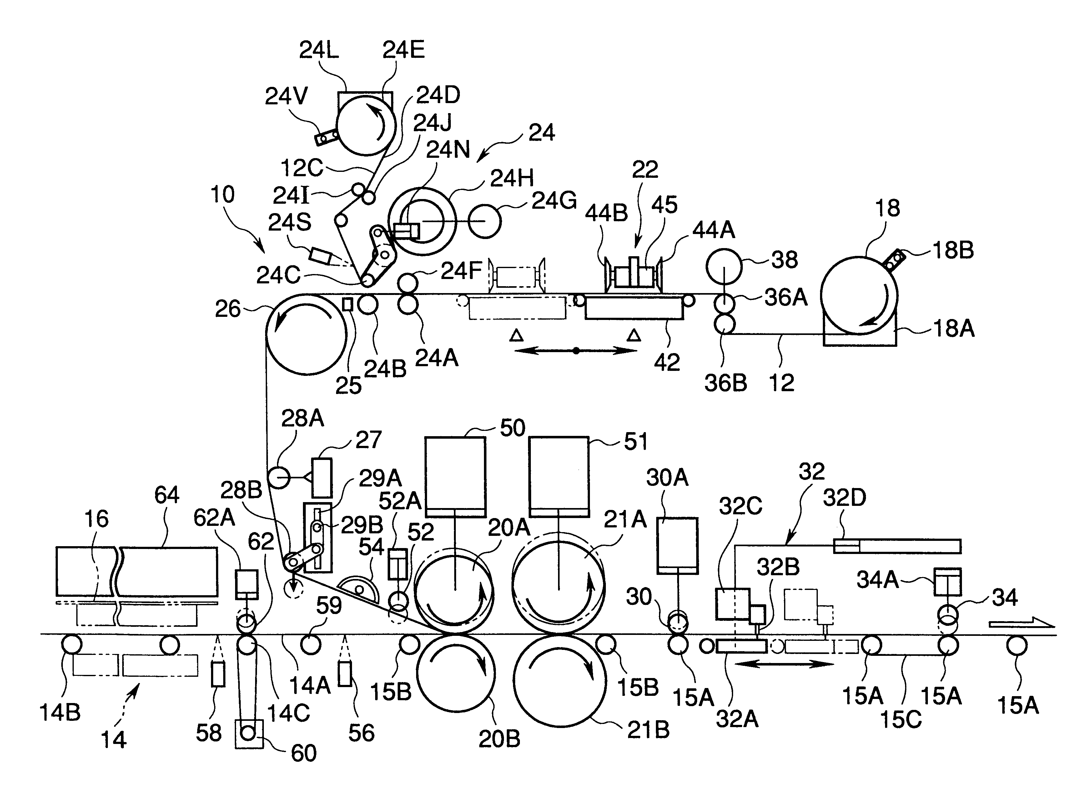
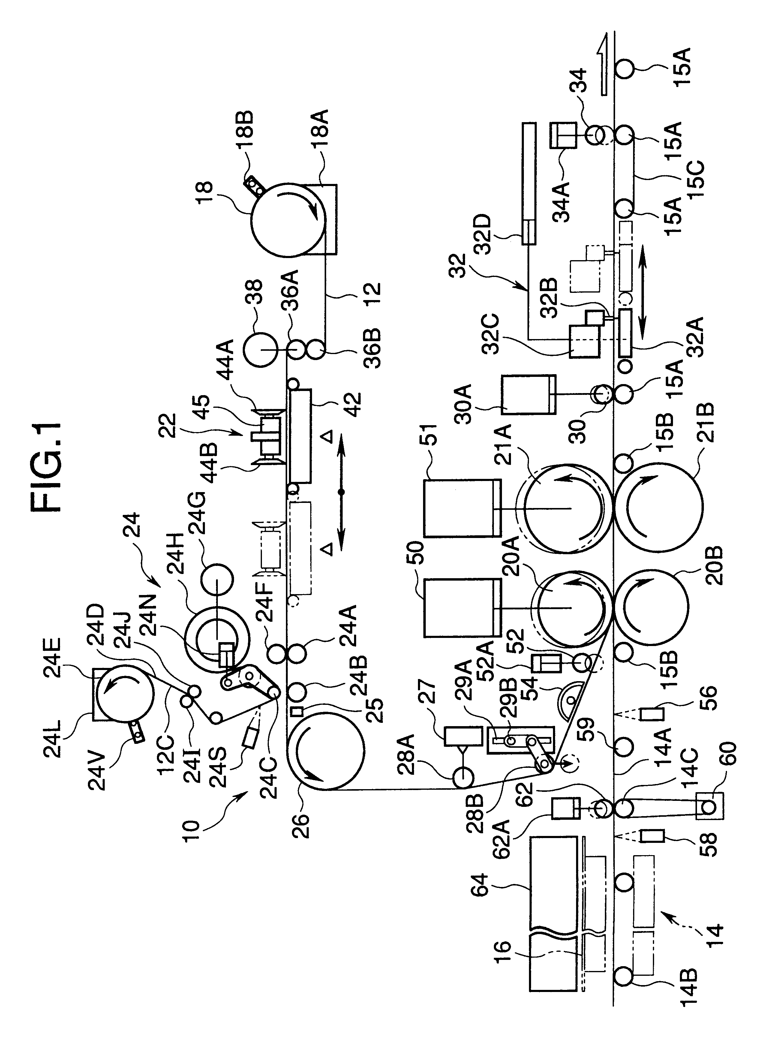
FIG. 1 shows a film applying apparatus 10 according to an embodiment of the present invention.

The film applying apparatus 10 comprises a substrate conveying device 14 for conveying a plurality of substrates 16 with width being 800 mm or more along a substrate conveying plane 14A at regular intervals in sequence, a film roll 18 where a laminated roll 12 as above described is rolled, and a half cutter 22, a cover film peeling device 24, a suction roll 26, a guide roll 28A in free rotation and a film guide roll 52 arranged between the film roll 18 and preparatory bonding rolls 20A, 20B in this order from the side of the film roll 18, and a cover film 12C of the laminated film 12 wound out from the film roll 18 is cut at the predetermined position by the half cutter 22 and half cutter line is formed. Next, among each half cut interline part of the cover film 12C, only a par...


PUM

PropertyMeasurementUnit
diameteraaaaaaaaaa
diameteraaaaaaaaaa
widthaaaaaaaaaa

Abstract

A film applying apparatus 10 is provided with preparatory bonding rolls 20A, 20B and laminating rolls 21A, 21B, and a laminated film 12 wound out from a film roll 18 and a substrate 16 conveyed by a substrate conveying device 14 pass between these rolls and pressure bonding is performed. Diameter of the preparatory bonding rolls 20A, 20B is made smaller than diameter of the laminating rolls 21A, 21B and range of elastic deformable area S1 at the roll surface at grasping starting of the substrate and the laminated film 12 by the preparatory bonding rolls 20A, 20B is made small thereby range of generating, air holding or the like is limited to small.

Description

1. Field of the InventionThe present invention relates to a film applying apparatus for applying a film to a surface of a substrate exemplified by a substrate for a printed circuit board or a glass substrate of a liquid crystal display device or a plasma display device by laminating rolls.2. Description of the Prior ArtIn a process for the manufacture of printed circuit boards used for electronic equipment such as computers, a laminated film consisting of a light-transmissible support film (a synthetic resin film usually represented by polyester), a photosensitive resin layer formed on the support film and a cover film covering the resin layer is applied onto a conductive surface layer of a substrate for a printed circuit board (substrate width being 610 mm usually and 650 mm at most) after the cover film is removed. And then a circuit pattern film is overlaid, and the photosensitive resin layer is exposed for a predetermined period of time via the circuit pattern film and the light...

Claims


Application Information

Patent Timeline
Patent Type & Authority Patents(United States)
IPC IPC(8): B32B37/14B32B38/10B32B37/22G03F7/16H05K3/00
CPCB32B37/226B32B38/10G03F7/16B32B2309/06B32B2457/08Y10T156/1741H05K3/0079Y10T156/1343B32B2457/20
Inventor KITAGAWA, KENJIYAMAMOTO, SHIGERU
Owner SOMAR CORP
Why Eureka
Try Eureka